Biomimetic Soft Actuators: An ISO-Inspired Methodology for Next-Gen Biomedical Device Development
This article presents a comprehensive ISO-inspired framework for biomimetic soft actuator design tailored for researchers and drug development professionals.
Biomimetic Soft Actuators: An ISO-Inspired Methodology for Next-Gen Biomedical Device Development
Abstract
This article presents a comprehensive ISO-inspired framework for biomimetic soft actuator design tailored for researchers and drug development professionals. We explore the foundational principles of bio-inspiration, detail a structured methodological pipeline from ideation to fabrication, address common challenges in performance optimization and biocompatibility, and establish validation protocols for benchmarking against conventional technologies. This guide aims to standardize and accelerate the translation of nature-inspired soft robotics into clinical and laboratory applications.
From Nature to Lab: Decoding Biological Principles for Soft Actuation
Application Notes for Soft Actuator Design Research
Within a thesis on ISO biomimetics methodology, the ISO 18458:2015 standard provides the foundational terminology and framework. For systematic bio-inspiration in soft robotics and actuator design, the process moves beyond simple analogy to a rigorous, documented methodology. This ensures repeatability, clarity, and effective knowledge transfer from biology to engineering.
The core principles involve:
- Analysis of the biological system (its function, structure, and underlying principles).
- Abstraction of the core functional principle, separating it from the specific biological context.
- Transfer of the abstracted principle to the technical domain.
- Implementation into a technical solution (e.g., a soft actuator).
For drug development, this framework can inspire novel delivery mechanisms (e.g., bacteriophage-inspired targeted delivery) or biodegradable actuator systems for implantable devices.
Table 1: Comparison of Bio-Inspired Actuation Mechanisms for Soft Robotics
| Biological Model | Abstracted Principle | Technical Implementation | Key Performance Metric (Typical Range) | Reference / State (2024) |
|---|---|---|---|---|
| Octopus Arm Musculature | Hydrostatic skeleton with muscle antagonism | Pneumatic/fluidic elastomer actuators (FEAs) | Blocking Force: 0.5 - 30 N; Strain: 40-300% | Prototype/Commercial Hybrid |
| Plant Cell Nastic Movements | Osmotic pressure-driven volume change | Hydrogel-based ionic actuators | Response Time: 10s - 1000s seconds; Stress: 1-100 kPa | Research Stage |
| Mammalian Skeletal Muscle | Hierarchical, aligned contraction under electrochemical signal | Electroactive polymers (e.g., DEAs, IPMCs) | Strain: 1-50%; Efficiency: <30% | Advanced Prototype |
| Bird Feather Interlocking | Directional, reversible attachment | Micro-structured polymer fibrils (e.g., for gripper surfaces) | Adhesion Strength: 1-50 kPa | Commercial Niche Products |
Experimental Protocols
Purpose: To systematically deconstruct a biological system for its actuation-relevant principles. Materials: Research literature databases, biological specimens/models, imaging software (e.g., Fiji/ImageJ), documentation tools. Procedure:
- Define the Function: Precisely state the biological actuation function (e.g., "rapid, power-amplified closing of mantis shrimp appendage for predation").
- Structural Analysis: Use imaging (micro-CT, SEM, microscopy) to quantify relevant structures. Measure geometries, layer thicknesses, material gradients.
- Mechanism Isolation: Identify the core mechanical/chemical/physical principle (e.g., "latched spring and latch release").
- Environment Context: Document the environmental conditions (aqueous, pH, temperature) under which the function is performed.
- Abstraction: Create a schematic or mathematical model describing only the core principle, devoid of biological specificities. This becomes the "bio-inspired design principle." Documentation: All steps must be recorded per ISO 18458 guidelines, creating a traceable "biologization" report.
Protocol 2: Validation of a Bio-Inspired Soft Actuator
Purpose: To test a fabricated soft actuator against the abstracted biological principle and performance benchmarks. Materials: Fabricated actuator, force/torque sensor, displacement/vision system, environmental chamber, data acquisition system, control software. Procedure:
- Benchmark Definition: Establish quantitative targets based on biological analysis (e.g., target strain energy density, specific force, response frequency).
- Static Performance Test:
- Mount actuator and apply controlled input (voltage, pressure, chemical stimulus).
- Measure output force/displacement at equilibrium.
- Calculate metrics: blocked force, free displacement, strain.
- Dynamic Performance Test:
- Apply cyclic input at varying frequencies.
- Record force-displacement hysteresis loops.
- Calculate work output per cycle, efficiency, bandwidth.
- Durability Test: Subject actuator to continuous or intermittent cycling (e.g., 1000+ cycles) and monitor performance degradation.
- Environmental Robustness: Test performance under varying conditions (temperature, humidity, fluid immersion) if relevant to application. Analysis: Compare results directly to the biological benchmark table and the abstracted model's predictions.
Diagrams
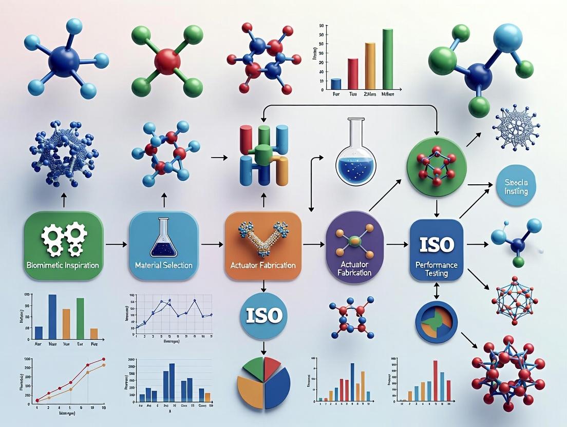
Diagram 1: ISO Biomimetics Process Flow
Diagram 2: Bio-Inspired Actuator R&D Workflow
The Scientist's Toolkit: Research Reagent Solutions
Table 2: Essential Materials for Biomimetic Soft Actuator Research
| Item / Reagent | Function in Research | Example / Note |
|---|---|---|
| Silicone Elastomers (PDMS) | Base material for fluidic/pneumatic soft actuators; high elasticity, biocompatible. | Sylgard 184, Ecoflex series. |
| Ionic Electrolytes | Enables ionically-conductive pathways for electroactive polymers (hydraulic or EAP). | 1-Ethyl-3-methylimidazolium salts, Lithium salts. |
| Hydrogel Precursors | Form swellable/contractile matrices for osmotically-driven actuators. | Poly(N-isopropylacrylamide), Alginate, Polyacrylamide. |
| Dielectric Elastomer Films | Key component for Dielectric Elastomer Actuators (DEAs); high dielectric strength. | VHB tape, polyurethane films. |
| Conductive Nanomaterials | Create flexible electrodes for EAPs or strain sensing. | Carbon black, graphene, PEDOT:PSS. |
| Microfabrication Molds (3D Printed) | Define the complex internal channels/structures of soft actuators. | Resin-based prints for high resolution. |
| Biocompatible Crosslinkers | For hydrogel or polymer actuators intended for in vivo drug delivery research. | Genipin, UV-initiated crosslinkers (LAP). |
| Simulation Software | Model abstracted biological principles & actuator performance (FEA). | COMSOL Multiphysics, Abaqus. |
Application Notes
This document details three archetypal biological actuators, providing a framework for their systematic study and biomimetic translation within the ISO Biomimetics methodology (ISO 18458:2015). These models exemplify distinct principles—contractile force, rapid elastic release, and osmotic-driven movement—offering a diverse toolkit for soft actuator design.
Vertebrate Skeletal Muscle: The Contractile Workhorse
A model for high-force, fatigue-resistant linear actuators. Function is based on the sliding filament theory, where actin and myosin filaments interact in a tightly regulated ATP-dependent cycle. Calcium signaling from the neuromuscular junction triggers the contraction via the troponin-tropomyosin complex.
Key Quantitative Parameters:
| Parameter | Typical Value / Range | Notes for Biomimetic Translation |
|---|---|---|
| Specific Power | ~50-100 W/kg | High efficiency target for artificial muscles. |
| Strain (Shortening) | 20-30% of resting length | A key target for electroactive polymer (EAP) actuators. |
| Contraction Speed | Varies with fiber type; ~0.1 to 10 muscle lengths/s | Design trade-off between speed and force. |
| Efficiency (Chem->Mech) | Up to ~25% | Significantly higher than many current synthetic actuators. |
| Activation/Relaxation Time | 10-100 ms | Dependent on Ca²⁺ sequestration and diffusion scales. |
Nematocyst (Cnidocyte): The Ultrafast Micro-Actuator
A model for single-use, ultra-high acceleration and power density micro-actuators. Harnesses stored elastic energy and osmotic pressure. The triggering mechanism involves a rapid influx of water into the capsule, generating pressures >150 atm to exert a stylet with extreme acceleration.
Key Quantitative Parameters:
| Parameter | Typical Value / Range | Notes for Biomimetic Translation |
|---|---|---|
| Discharge Time | < 1 ms | Ultrafast response is a key biomimetic target. |
| Acceleration | > 5,000,000 g | For the penetrating stylet; relevant for micro-puncture systems. |
| Pressure in Capsule | 150+ atm (15+ MPa) | High energy density storage in polymeric matrix. |
| Power Density | ~1 GW/kg (est.) | Extraordinarily high due to elastic release mechanism. |
Plant Movements (e.g., Trap Closure, Leaf Folding): Osmotic/Hygroscopic Actuators
Models for energy-efficient, distributed actuation without dedicated muscle tissue. Movements are driven by turgor pressure changes or differential swelling/shrinkage in cell walls (seismonasty, thigmonasty). Mimosa pudica and Dionaea muscipula (Venus flytrap) are key models.
Key Quantitative Parameters:
| Parameter | Typical Value / Range | Notes for Biomimetic Translation |
|---|---|---|
| Actuation Time (Fast) | 100 ms (Flytrap) to 1-2 s (Mimosa) | Slower than nematocysts but energy-efficient. |
| Driving Pressure | 0.1 - 1.5 MPa (Turgor Pressure) | Lower pressure, distributed mechanism. |
| Stimulus | Mechanical, Chemical, Light | Offers multi-modal sensing/actuation integration. |
| Cycle Life | Many cycles (reversible) | Advantage over single-use nematocyst model. |
Experimental Protocols
Protocol 1: In Vitro Muscle Contractility Assay (Skinned Fiber Preparation)
Objective: To isolate the core contractile apparatus for direct study of actin-myosin mechanics and screening of biomimetic compounds. Materials: See "The Scientist's Toolkit" below. Procedure:
- Tissue Acquisition & Dissection: Excise a small muscle bundle (e.g., rabbit psoas) in relaxing solution. Pin to a silicone dish and carefully dissect a single fiber segment (1-2 mm long).
- Skinning: Permeabilize the sarcolemma by incubating the fiber in skinning solution (1% Triton X-100 in relaxing solution) for 30 min at 4°C.
- Apparatus Mounting: Use micro-tweezers to attach the ends of the skinned fiber to a force transducer and a length controller motor in an experimental chamber.
- Activation & Data Collection: Submerge fiber in pre-activation solution (low Ca²⁺) for 2 min. Rapidly transfer to activation solution (pCa 4.5). Measure isometric force development. Vary [Ca²⁺] to generate a force-pCa relationship curve.
- Relaxation & Analysis: Return fiber to relaxing solution. Analyze force trace for parameters like peak tension, activation/relaxation rates, and calcium sensitivity.
Protocol 2: Nematocyst Discharge Triggering & Kinematic Analysis
Objective: To quantify the discharge kinetics and stimulus-response pathway of isolated nematocysts. Materials: Sea anemone (Aiptasia sp.) or hydra culture, chemotactic stimulants (e.g., GSH, N-acetylated sugars), high-speed camera (>100,000 fps). Procedure:
- Isolation: Gently homogenize tentacle tissue in isotonic, Ca²⁺-free solution. Filter through mesh and centrifuge at low speed to pellet nematocysts.
- Microscopy Setup: Place a drop of nematocyst suspension on a slide. Mount on an inverted microscope equipped with a high-speed camera.
- Stimulus Application: Using a micro-injector, introduce a known chemical trigger (e.g., 10 mM GSH) into the suspension near the field of view.
- High-Speed Recording: Initiate recording just prior to stimulus application. Capture the entire discharge event.
- Image Analysis: Use tracking software to measure stylet velocity and acceleration. Correlate discharge events with time of stimulus contact.
Protocol 3: Quantifying Plant Movement via Digital Image Correlation (DIC)
Objective: To map strain fields and movement kinematics in plant actuators like the Venus flytrap. Materials: Dionaea muscipula plant, fine-tipped stimulator, speckle pattern kit (non-toxic paint), stereo or high-resolution cameras, DIC software. Procedure:
- Sample Preparation: Apply a fine, random speckle pattern to the inner surface of the trap lobe using white/black acrylic paint.
- Calibration: Place the plant in front of calibrated cameras. Capture an image of a calibration target.
- Baseline Acquisition: Record 30 s of video of the untriggered trap at high frame rate (e.g., 500 fps).
- Stimulation & Recording: Gently trigger mechanosensitive hairs (2 touches within ~30 s) using a fine probe. Continue recording until trap is fully closed and begins to reopen.
- DIC Processing: Import image sequence to DIC software (e.g., GOM Correlate, Noorr). Define reference image (pre-stimulation) and compute displacement and strain fields over time. Analyze curvature change and propagation of the "wave" of movement.
The Scientist's Toolkit
| Reagent / Material | Function in Research |
|---|---|
| Skinned Fiber Relaxing/Activating Solutions | Precisely control ionic environment (Mg²⁺, ATP, Ca²⁺ buffered with EGTA) to study contractile apparatus in isolation. |
| Triton X-100 | Non-ionic detergent used to permeabilize (skin) the muscle fiber membrane, allowing experimental control of the intracellular milieu. |
| Glutathione (GSH) | A key chemical trigger used to stimulate nematocyst discharge in experimental settings, mimicking prey contact. |
| Piezoelectric Force Transducer | Measures micro-Newton level forces generated by single muscle fibers or small tissue samples in vitro. |
| High-Speed Camera (>100k fps) | Essential for capturing ultrafast biological actuation events like nematocyst discharge or trap closure. |
| Digital Image Correlation (DIC) Software | Analyzes full-field, non-contact deformation and strain in complex biological structures like moving plant traps. |
| Ionophores (e.g., A23187) | Used in muscle or plant studies to artificially manipulate intracellular Ca²⁺ levels, probing calcium's role in actuation. |
Diagrams
Title: Vertebrate Skeletal Muscle Activation Signaling Pathway
Title: Experimental Workflow for Nematocyst Discharge Analysis
Title: Logic of Fast Plant Movement via Osmotic Actuation
Application Notes within ISO Biomimetics Methodology for Soft Actuator Design
The ISO biomimetics methodology (ISO 18458) provides a structured framework for translating biological principles into technical applications. Within this context, soft actuator research leverages biological inspiration—such as muscular contraction, plant nastic movements, and cellular mechanotransduction—to engineer adaptive, energy-efficient systems. The following materials are central to this paradigm.
Hydrogels emulate the hydrated extracellular matrix and soft tissues. Their biomimetic application focuses on stimulus-responsive swelling/contraction for controlled motion and drug release. Dielectric Elastomers mimic the fast, high-strain response of muscular tissues, utilizing electrostatic pressures for actuation. Liquid Crystal Elastomers combine the anisotropic order of liquid crystals with rubber elasticity, mirroring the orchestrated, directional actuation seen in biological systems.
The integration of these materials into the ISO biomimetics workflow involves: 1) Identification of a biological principle (e.g., tendril coiling), 2) Abstraction of its functional mechanism, 3) Transfer to a technical model specifying material requirements, and 4) Implementation via synthesis and prototyping of these advanced materials.
Quantitative Material Property Comparison
Table 1: Key Performance Metrics for Biomimetic Soft Actuator Materials
| Material Class | Typical Strain (%) | Response Speed | Actuation Stress (kPa) | Key Stimulus | Energy Density (kJ/m³) |
|---|---|---|---|---|---|
| Hydrogels (pH-responsive) | 10 - 200 | Seconds to Minutes | 1 - 50 | pH, Ionic Strength, Temperature | 0.1 - 10 |
| Dielectric Elastomers (VHB 4910) | 10 - 100 | Milliseconds to Seconds | 10 - 100 | Electric Field (kV/mm) | 10 - 100 |
| Liquid Crystal Elastomers (Monodomain) | 20 - 100 | Seconds to Minutes | 10 - 200 | Temperature, Light | 1 - 50 |
Experimental Protocols
Protocol 1: Synthesis of pH-Responsive Polyacrylamide-Co-Acrylic Acid Hydrogel Actuator
Objective: To create a bilayer hydrogel actuator that mimics plant hygroscopic movement via differential swelling. Materials: Acrylamide (AAm), Acrylic acid (AAc), N,N'-Methylenebisacrylamide (MBAA, crosslinker), Ammonium persulfate (APS, initiator), N,N,N',N'-Tetramethylethylenediamine (TEMED, accelerator). Procedure:
- Prepare two pre-gel solutions in separate vials.
- Layer 1 (Low Responsiveness): 1.5 M AAm, 0.1 M AAc, 0.01 mol% MBAA (relative to monomers) in deionized water.
- Layer 2 (High Responsiveness): 0.5 M AAm, 1.0 M AAc, 0.01 mol% MBAA.
- Degas both solutions with nitrogen for 10 minutes.
- Add 10 µL of 10% w/v APS and 2 µL TEMED per mL of solution to each vial and mix gently.
- Immediately pipette Layer 1 solution into a rectangular silicone mold. Allow to gel for 5 minutes at room temperature.
- Carefully pipette Layer 2 solution on top of the partially gelled first layer. Cover and let polymerize for 1 hour.
- Demold the bilayer strip and equilibrate in deionized water for 24 hours, changing water 3 times.
- Actuation Test: Immerse the strip (10mm x 3mm x 0.5mm) in buffers of pH 3 and pH 9. Record the curvature change over time using a digital camera. Calculate radius of curvature from image analysis.
Protocol 2: Fabrication and Actuation of a Dielectric Elastomer Actuator (DEA)
Objective: To construct a planar dielectric elastomer minimum energy structure (DEMES) actuator inspired by insect wing kinematics. Materials: VHB 4910 film (3M), Carbon conductive grease (or compliant electrode material), Acrylic frame, High-voltage amplifier (0-10 kV). Procedure:
- Biaxially pre-stretch a VHB 4910 film to 300% x 300% and mount on a rigid acrylic frame.
- Apply carbon conductive grease in a circular pattern (diameter 20mm) on both sides of the stretched film to form compliant electrodes.
- Attach a lightweight, rigid plastic disk to the central electrode area on one side.
- Connect the electrodes to the high-voltage amplifier using insulated copper wires.
- Actuation Test: Place the actuator under a laser displacement sensor. In a fume hood, apply a step voltage from 0 to 5 kV at a ramp rate of 500 V/s. Measure the resulting out-of-plane displacement of the central disk. Record displacement vs. applied voltage. Observe all high-voltage safety protocols.
Protocol 3: Photothermal Actuation of a Liquid Crystal Elastomer (LCE) Film
Objective: To demonstrate directional contraction of a monodomain LCE under near-infrared (NIR) light, mimicking a linear contractile unit. Materials: RM82 mesogen, 1,4-Bis-[4-(3-acryloyloxypropyloxy)benzoyloxy]-2-methylbenzene (crosslinker), 2,6-Di-tert-butyl-4-methylphenol (inhibitor), 2-Methoxy-4-phenylphenyldiazonium hexafluorophosphate (photoinitiator). Procedure:
- Synthesize the LCE film via a two-step “click” reaction or acquire a pre-aligned monodomain LCE film.
- Cut a rectangular strip (15mm x 2mm) along the nematic director (alignment direction).
- Clamp one end of the strip to a fixed stand. Attach the other end to a low-force load cell or a marker for video tracking.
- Position an NIR laser (808 nm, 1 W/cm² power density) to illuminate the entire strip. Use a safety shield.
- Actuation Test: Irradiate the strip for 10 seconds. Record the force or displacement change. Allow to cool and return to original length. Measure the strain as ∆L/L₀. Repeat at different power densities to characterize the photothermal response.
Diagrams
Diagram 1: ISO Biomimetics Workflow Driving Material Selection
Diagram 2: Hydrogel Actuation via pH-Triggered Swelling Differential
The Scientist's Toolkit: Essential Research Reagents & Materials
Table 2: Key Reagents for Soft Actuator Fabrication and Characterization
| Item | Function in Research | Example Use Case |
|---|---|---|
| VHB 4910 Elastomer (3M) | High-strain dielectric elastomer film, serves as the dielectric/elastic matrix in DEAs. | Creating fast, large-strain actuators for biomimetic robots. |
| Carbon Conductive Grease | Compliant, stretchable electrode material for DEAs. Maintains conductivity under large deformation. | Forming electrodes on pre-stretched VHB films. |
| RM82 Liquid Crystal Monomer | A common diacrylate mesogen used to synthesize LCEs with a nematic-to-isotropic transition. | Fabricating photomechanical or thermal LCE actuators. |
| Photoinitiator (e.g., DMPA) | Initiates free-radical polymerization upon UV light exposure for crosslinking polymers. | Curing hydrogel or LCE networks in specific geometries. |
| N,N'-Methylenebisacrylamide (MBAA) | A common crosslinker for polyacrylamide hydrogels; controls network density and mechanical properties. | Tuning the stiffness and swelling ratio of responsive hydrogels. |
| High-Voltage Amplifier (0-10 kV) | Provides the controlled high-voltage electric field required to actuate dielectric elastomers. | Driving DEAs in laboratory experiments and prototypes. |
| Near-Infrared (NIR) Laser Diode (808 nm) | Provides photothermal stimulus for light-responsive materials like LCEs doped with absorbers. | Triggering remote, spatially controlled actuation in LCEs. |
| Micro-Mechanical Testing System | Measures force and displacement of soft materials with high sensitivity (mN/mm resolution). | Characterizing the stress-strain behavior of hydrogel and LCE films. |
The design of biomimetic soft actuators, guided by the ISO 18458:2015 framework on biomimetics, requires a fundamental understanding of actuation mechanisms. This document provides application notes and standardized protocols for researching pneumatic, hydraulic, electroactive, and thermal actuation mechanisms, focusing on their integration into a systematic, bio-inspired design process for applications in advanced robotics and biomedical devices.
Application Notes & Comparative Analysis
Pneumatic Actuation
Principle: Controlled expansion of elastomeric chambers or bladders via pressurized air or gas. Biomimetic Analogue: Muscular hydrostats (e.g., octopus arms, elephant trunks). Key Application: Soft grippers, wearable exoskeletons, pneumatic artificial muscles (PAMs). Advantages: High power-to-weight ratio, fast response, relatively simple construction. Limitations: Requires a pressure source (pump/compressor), bulky external components, limited portability. Current Research Focus: Development of lightweight, portable microcompressors and efficient, embedded valve systems.
Hydraulic Actuation
Principle: Use of incompressible fluid (often water or oil) to transmit force and displacement. Biomimetic Analogue: Vascular systems, plant cell turgor pressure, echinoderm podia. Key Application: High-force robotic manipulators, underwater soft robots, tunable lenses. Advantages: Very high force and torque density, precise motion control, self-lubricating. Limitations: Risk of leakage, requires pumps and fluid reservoirs, can be slower than pneumatic. Current Research Focus: Self-healing fluidic channels and magnetorheological/electrorheological working fluids for dynamic stiffness control.
Electroactive Polymer (EAP) Actuation
Principle: Dimensional change in polymeric materials in response to an electric field. Major types include dielectric elastomer actuators (DEAs) and ionic polymer-metal composites (IPMCs). Biomimetic Analogue: Fast biological tissues (e.g., hummingbird wings, jellyfish bell pulsation). Key Application: Micro-pumps, biomimetic swimmers, tactile displays, dynamic braille interfaces. Advantages: Direct electrical control, silent operation, high energy density (DEAs), low voltage operation (IPMCs). Limitations: Requires high voltage (DEAs), often operates in liquid electrolyte (IPMCs), susceptible to electromechanical instability. Current Research Focus: Enhancing dielectric constant of elastomers, developing solid-state ionic polymers, and improving electrode conductivity and stretchability.
Thermal Response Actuation
Principle: Utilization of material deformation due to thermal expansion or phase change (e.g., shape memory polymers/SMPs, shape memory alloys/SMAs, liquid crystal elastomers/LCEs). Biomimetic Analogue: Pine cone hygroscopic opening, helical seed dispersal mechanisms. Key Application: Self-deploying structures, minimally invasive surgical tools, adaptive textiles. Advantages: Can generate large strokes and forces, capable of locking in shape (SMPs/SMAs). Limitations: Low energy efficiency (heat loss), slow cooling cycles, challenging to control precisely. Current Research Focus: Photothermal actuation using nanocomposites for contactless control and multi-stimuli responsive materials.
Quantitative Comparison of Actuation Mechanisms
Table 1: Performance Metrics of Fundamental Actuation Mechanisms
| Mechanism | Typical Strain (%) | Typical Stress (MPa) | Bandwidth (Hz) | Efficiency (%) | Power Density (W/kg) |
|---|---|---|---|---|---|
| Pneumatic | 20 - 500 | 0.1 - 2.0 | 0 - 100 | 20 - 40 | 500 - 5000 |
| Hydraulic | 10 - 100 | 0.5 - 10.0 | 0 - 50 | 60 - 80 | 1000 - 10000 |
| DEA | 10 - 300 | 0.1 - 7.0 | 1 - 10000 | 60 - 90 | 100 - 10000 |
| IPMC | 0.1 - 5.0 | 1.0 - 30.0 | 0.1 - 100 | 0.1 - 2.0 | 0.1 - 10 |
| SMA (NiTi) | 1 - 8 | 50 - 500 | 0 - 10 | < 10 | Up to 10000 |
| LCE | 20 - 400 | 0.1 - 1.0 | 0.01 - 1 | N/A | N/A |
Data compiled from recent literature (2022-2024). Values are typical ranges and are highly dependent on specific material and geometric parameters.
Experimental Protocols
Protocol 1: Characterization of a Dielectric Elastomer Actuator (DEA)
Objective: To measure the actuation strain and blocked force of a circular DEA under varying voltage. Methodology:
- Fabrication: Cast a silicone elastomer (e.g., Ecoflex 00-30) membrane (~100 µm thick). Spray-coat or brush-on compliant electrodes (carbon grease or carbon black/silicone mixture) on both sides in a circular active area.
- Mounting: Clamp the DEA at its perimeter in a rigid fixture. For strain measurement, attach a non-contact laser displacement sensor pointed at the center. For blocked force, mount actuator against a micro-load cell.
- Actuation: Use a high-voltage amplifier to apply a stepped DC voltage from 0 to a predefined maximum (e.g., 5kV) with 500V increments.
- Data Acquisition: At each voltage step, record the displacement (for strain calculation) and/or the force reading (under blocked conditions) after a 10-second stabilization period.
- Analysis: Calculate areal strain from displacement. Plot voltage vs. strain and voltage vs. blocked force. Determine the breakdown voltage and maximum strain energy density.
Protocol 2: Testing of a Pneumatic Network (PneuNet) Actuator
Objective: To quantify the bending angle and tip force of a soft PneuNet bending actuator. Methodology:
- Preparation: Fabricate a PneuNet actuator via soft lithography using a two-part silicone (e.g., Dragon Skin 10).
- Setup: Secure the actuator base. Connect its inlet to a digital pressure regulator and air supply.
- Bending Kinematics: Position a digital camera perpendicular to the bending plane. Apply pressure in steps (e.g., 0, 10, 20, ..., 100 kPa). At each step, capture an image after a 5-second delay.
- Force Measurement: Position the actuator horizontally. Place a digital force gauge at the actuator tip height. Pressurize to target pressure and advance the actuator until contact; record the peak force at a fixed tip displacement (e.g., 5 mm).
- Analysis: Use image processing software to measure the bending angle from images. Correlate pressure with bending angle and tip force.
Protocol 3: Characterization of a Shape Memory Polymer (SMP) Actuator
Objective: To analyze the shape recovery and recovery force of a thermally-activated SMP. Methodology:
- Sample Programming: Heat an SMP strip (e.g., polyurethane-based) above its glass transition temperature (Tg). Deform it into a temporary shape (e.g., coiled). Cool it below Tg while constrained to fix the temporary shape.
- Recovery Kinematics: Suspend the programmed sample in a temperature-controlled chamber with a camera. Heat the chamber at a constant rate (e.g., 2°C/min) from below Tg to above Tg. Record video.
- Recovery Force: Program a sample and place it in a tensile tester with environmental chamber. Constrain its length to the original temporary shape. Heat as in step 2 while measuring the generated stress.
- Analysis: From video, plot recovery ratio (recovered angle/original angle) vs. temperature. From force data, plot recovery stress vs. temperature.
Visualizations
Diagram 1: Pneumatic Actuator Design Workflow
Diagram 2: Stimulus-Transduction-Response Pathways
The Scientist's Toolkit: Research Reagent Solutions
Table 2: Essential Materials for Soft Actuator Research
| Material/Reagent | Typical Product Example | Function in Research |
|---|---|---|
| Silicone Elastomer | Ecoflex 00-30 (Smooth-On) | High-stretch, soft matrix for pneumatic/hydraulic actuators and DEA membranes. |
| Dielectric Gel | Sylgard 527 (Dow) | Low-modulus, high dielectric constant filler for composite DEAs. |
| Compliant Electrode | Carbon Grease (MG Chemicals) | Conductive, stretchable electrode for dielectric elastomer actuators. |
| Ionic Liquid | 1-Ethyl-3-methylimidazolium tetrafluoroborate ([EMIM][BF4]) | Electrolyte for ionic EAPs (IPMCs) and functionalizing polymers. |
| Shape Memory Polymer | Veriflex (Mitsubishi) | Thermoset resin that exhibits shape memory effect upon heating. |
| Liquid Crystal Elastomer | Prepared from RM257 mesogen | Provides large, reversible contraction upon thermal/optical stimulus. |
| Carbon Nanotubes | SWCNTs (Sigma-Aldrich) | Additive for enhancing electrical/thermal conductivity and mechanical strength. |
| Photo-thermal Dye | Sudan Black B | Absorbs near-infrared light, converting it to heat for remote actuation of thermal actuators. |
| Agarose Gel | Low-melt Temperature Agarose | Used as a hydraulic/ionic conductor in bio-hybrid or edible actuator models. |
| Ferrofluid | EMG 700 (Ferrotec) | Colloidal magnetic particles for magnetically-responsive hydraulic or composite actuators. |
A Step-by-Step Design Pipeline: Fabricating Biomimetic Soft Actuators for Biomedicine
Within the ISO biomimetics methodology (ISO 18458) for soft actuator design, Phase 1 constitutes the critical biological foundation. This phase involves the systematic deconstruction of a biological system—such as muscle contraction, ciliary beating, or plant cell nastic movements—to extract its core functional principles. These abstracted principles then inform engineering specifications. For drug development, this analytical phase parallels target identification and validation, where understanding pathological signaling pathways reveals points for therapeutic intervention. The following Application Notes and Protocols detail the experimental and analytical workflows for this phase.
Core Quantitative Analysis: Muscle Contraction Kinetics
Table 1: Comparative Kinetics of Key Molecular Motors in Muscle Contraction
| Motor Protein | System Source | Max Velocity (µm/s) | Force Production (pN) | ATP Turnover Rate (s⁻¹) | Primary Regulatory Mechanism |
|---|---|---|---|---|---|
| Myosin II | Rabbit psoas muscle | ~7.5 | 2-6 | ~15 | Ca²⁺ via Troponin/Tropomyosin |
| Myosin V | Processive cargo transport | ~0.45 | 2-3 | ~25 | Ca²⁺ & cargo binding |
| Myosin VI | Intracellular trafficking | ~0.65 | 2-3 | ~10 | Dimerization & cargo binding |
| Kinesin-1 | Axonal transport (reference) | ~1.0 | 5-7 | ~80 | Auto-inhibition & cargo binding |
Table 2: Key Ion Concentrations in Skeletal Muscle Excitation-Contraction Coupling
| Ion / Molecule | Resting Cytosol | Peak Activated Cytosol | Sarcoplasmic Reticulum Lumen | Key Functional Impact |
|---|---|---|---|---|
| Calcium (Ca²⁺) | 0.1 µM | 1-10 µM | 1-10 mM | Triggers troponin movement |
| Sodium (Na⁺) | 10-15 mM | ~30 mM | 10-15 mM | Initiates action potential |
| Potassium (K⁺) | 140 mM | ~139 mM | 140 mM | Repolarizes membrane |
| ATP | ~5 mM | ~4.8 mM | - | Energy for power stroke & pumping |
Experimental Protocols
Protocol 1: In Vitro Motility Assay (IVMA) for Myosin Function
Objective: To quantify the sliding velocity of actin filaments propelled by myosin motors adsorbed to a surface, abstracting the force-velocity relationship. Materials: Purified myosin, F-actin (labeled with rhodamine-phalloidin), ATP, motility buffer, nitrocellulose-coated flow cell, fluorescence microscope with TIRF capability. Procedure:
- Surface Preparation: Perfuse a 0.1% nitrocellulose solution into a flow cell and allow to dry.
- Motor Adsorption: Introduce 50 µg/mL myosin in high-salt buffer (300 mM KCl) for 2 minutes. Wash with low-salt buffer (25 mM KCl).
- Blocking: Perfuse 1 mg/mL bovine serum albumin (BSA) to block non-specific binding.
- Actin Introduction: Introduce 20 nM rhodamine-labeled F-actin in motility buffer (25 mM imidazole, pH 7.4, 25 mM KCl, 4 mM MgCl₂, 1 mM EGTA).
- Initiation of Motility: Perfuse motility buffer containing 2 mM ATP and an oxygen-scavenging system (0.1 mg/mL glucose oxidase, 0.02 mg/mL catalase, 3 mg/mL glucose).
- Data Acquisition: Record filament movement at 5-10 fps for 60 seconds.
- Analysis: Use tracking software (e.g., ImageJ TrackMate) to determine mean filament velocity from >100 filaments across 3+ experiments.
Protocol 2: Calcium Transient Measurement in Single Muscle Cells
Objective: To spatially and temporally map intracellular Ca²⁺ dynamics during excitation-contraction coupling. Materials: Isolated flexor digitorum brevis (FDB) muscle fibers, Fura-2 AM dye (5 µM), physiological Ringer's solution, field stimulation apparatus, ratiometric fluorescence imaging system. Procedure:
- Cell Preparation: Isolate FDB fibers via collagenase digestion (2 mg/mL, 37°C, 90 min).
- Dye Loading: Incubate fibers in Ringer's with Fura-2 AM and 0.02% Pluronic F-127 for 30 min at room temperature. Wash thoroughly.
- Mounting & Stimulation: Place fiber in a stimulation chamber. Deliver 1-5 ms pulses at 1-50 Hz via parallel platinum electrodes.
- Imaging: Capture alternating 340 nm and 380 nm excitation images, measuring emission at 510 nm. Calculate ratio (R = F₃₄₀/F₃₈₀) every 10 ms.
- Calibration: Perform in situ calibration using 10 µM ionomycin with high-Ca²⁺ (Rmax) and Ca²⁺-free (Rmin) buffers to convert ratio to [Ca²⁺].
The Scientist's Toolkit: Key Research Reagents
| Item / Reagent | Primary Function in Phase 1 Analysis |
|---|---|
| Rhodamine-Phalloidin | High-affinity fluorescent probe for staining and visualizing filamentous actin (F-actin). |
| Fura-2, AM ester | Ratiometric, cell-permeant calcium indicator for quantitative live-cell [Ca²⁺] measurement. |
| Ionomycin | Calcium ionophore used for calibrating fluorescent Ca²⁺ indicators by saturating chelators. |
| ATPγS (Adenosine 5′-[γ-thio]triphosphate) | Non-hydrolyzable ATP analog used to study myosin binding states and inhibit motility. |
| Blebbistatin | Specific, reversible inhibitor of myosin II ATPase, used to dissect its role in contraction. |
| Troponin C Antibody (Clone JLT-12) | Monoclonal antibody for immuno-localization and quantification of troponin complex in tissue. |
| Collagenase Type IV | Enzyme for gentle dissociation of intact, viable single muscle fibers from tissue. |
| Pluronic F-127 | Non-ionic surfactant to disperse hydrophobic dyes (e.g., Fura-2 AM) in aqueous solutions. |
Visualizations
Title: Biomimetic Abstraction Workflow from Muscle to Specs
Title: Excitation-Contraction Coupling Signaling Pathway
Within the ISO biomimetics methodology for soft actuator design, Phase 2 transforms qualitative biological principles from Phase 1 into quantitative, predictive computational frameworks. This phase is critical for translating the dynamics of biological signaling pathways (e.g., calcium-mediated muscle contraction, hormone-triggered shape change) into engineering models for stimuli-responsive soft actuators. For researchers and drug development professionals, these models serve as virtual testbeds, enabling rapid iteration of material compositions, geometry, and stimulus application to optimize actuator performance for applications such as targeted drug delivery systems and biomedical robotics.
Core Computational Models & Quantitative Data
This section outlines the primary physics-based models used to simulate biomimetic soft actuator behavior. The following table summarizes key model parameters and their biological correlates.
Table 1: Multi-Physics Models for Biomimetic Soft Actuator Simulation
| Physics Domain | Governing Equations/Theory | Key Model Parameters (Typical Range/Unit) | Biological Analogue in Actuation | Primary Simulation Output |
|---|---|---|---|---|
| Nonlinear Solid Mechanics | Neo-Hookean, Ogden, or Arruda-Boyce hyperelasticity; Finite Strain Theory. | Young’s Modulus, E (10 kPa - 1 MPa); Poisson’s ratio, ν (~0.49); Strain energy density coefficients (C10, C01). | Tissue elasticity and large deformations. | Stress/Strain fields, deformation geometry. |
| Electro-Chemo-Mechanics | Nernst-Planck-Poisson equations coupled with swelling stress. | Ion concentration (0.1 - 2.0 M); Diffusion coefficient, D (1e-11 - 1e-9 m²/s); Fixed charge density (0.1 - 5.0 mM). | Ion flux in cellular signaling (e.g., Ca²⁺, K⁺). | Swelling ratio, bending curvature, response time. |
| Thermo-Mechanics | Heat transfer equation coupled with thermal expansion. | Coefficient of thermal expansion, α (0.1 - 1.0 x 10⁻³ /K); Thermal conductivity, k (0.1 - 0.5 W/(m·K)). | Thermoreceptor triggering mechanisms. | Actuation stroke vs. temperature. |
| Fluid-Structure Interaction (FSI) | Navier-Stokes equations coupled with solid mechanics. | Fluid viscosity, μ (0.001 - 10 Pa·s); Reynolds number, Re (<1 for micro-scale). | Hydraulic actuation in plants/vascular systems. | Flow-induced deformation, pressure distribution. |
| Photothermal Actuation | Helmholtz equation for light absorption, coupled with thermo-mechanics. | Absorption coefficient (1 - 100 cm⁻¹); Photothermal conversion efficiency (η: 0.2 - 0.9). | Light-triggered biological processes. | Transient temperature and displacement fields. |
Detailed Experimental Protocols for Model Validation
The following protocols are essential for generating empirical data to calibrate and validate the computational models described above.
Protocol 3.1: Calibration of Electro-Chemo-Mechanical Model for Ionic Hydrogel Actuators
- Objective: To determine the material parameters (diffusion coefficient, fixed charge density) for simulating pH- or ion-driven actuation.
- Materials: See "The Scientist's Toolkit" (Section 5).
- Procedure:
- Sample Preparation: Fabricate hydrogel actuators (e.g., via mold casting or 3D printing) using a charged polymer (e.g., polyacrylic acid).
- Equilibrium Swelling Test:
- Immerse samples in buffer solutions of varying ionic strength (0.01M - 1.0M NaCl) and pH (4.0 - 10.0).
- Measure dimensional change (diameter, length) at equilibrium (24-48 hrs) using digital calipers or microscopy.
- Calculate volumetric swelling ratio, Q.
- Dynamic Response Test:
- Rapidly transfer a pre-equilibrated sample to a new solution with a different ion concentration/pH.
- Record the bending curvature or length change over time using a high-speed camera.
- Extract the characteristic response time (τ).
- Parameter Fitting: Use the equilibrium swelling data (Q vs. ion concentration) to inversely determine the fixed charge density and polymer-solvent interaction parameter via fitting to the Flory-Rehner theory extended with ionic terms. Use the dynamic response (τ) to estimate the effective diffusion coefficient.
Protocol 3.2: Validation of FSI Model for Pneumatic/Hydraulic Actuators
- Objective: To validate simulated actuator deformation against experimental data under fluid pressure loading.
- Materials: See "The Scientist's Toolkit" (Section 5).
- Procedure:
- Actuator Instrumentation: Fabricate a soft pneumatic actuator (e.g., a PneuNet design from elastomer). Embed or surface-attach fiber Bragg grating (FBG) sensors at critical points (chamber walls, bending tip) for strain mapping.
- Controlled Pressure Input: Connect the actuator to a programmable pressure regulator. Apply a step or ramp pressure input (0 to 50 kPa, at 5 kPa increments).
- Synchronized Data Acquisition:
- Record real-time strain data from all FBG sensors.
- Simultaneously capture actuator deformation using a synchronized 3D motion capture system with high-resolution cameras.
- Record the applied pressure from the regulator.
- Model Validation Workflow:
- Replicate the exact actuator geometry and material model (e.g., Yeoh hyperelastic) in the FSI simulation software.
- Apply the identical pressure boundary condition.
- Compare the simulated strain field and final deformed shape with the experimental FBG and motion capture data. Iteratively refine material parameters until error (e.g., RMS) is minimized.
Visualization of Computational Workflows
Title: Computational Validation Workflow for Biomimetic Actuators
Title: Multi-Physics Couplings in Stimuli-Responsive Actuation
The Scientist's Toolkit: Research Reagent Solutions & Essential Materials
Table 2: Essential Tools for Computational & Experimental Phase 2 Research
| Item/Category | Specific Example/Product | Function in Phase 2 |
|---|---|---|
| Multi-Physics Simulation Software | COMSOL Multiphysics, ANSYS Mechanical/Fluent, Abaqus FEA. | Provides integrated solvers for coupling mechanical, chemical, thermal, and electrical physics in a single simulation environment. Essential for predictive modeling. |
| Hyperelastic Material Tester | Instron ElectroPuls, uniaxial/biaxial tensile testers with video extensometry. | Generates stress-strain data under various loads to calibrate material models (e.g., Ogden coefficients) for simulation accuracy. |
| Programmable Fluidic System | Elveflow OB1 or Fluigent pressure/flow controllers with microfluidic chips. | Precisely applies pneumatic/hydraulic pressure inputs to soft actuators for dynamic FSI model validation (Protocol 3.2). |
| High-Speed 3D Deformation Capture | Digital Image Correlation (DIC) systems (e.g., Correlated Solutions), multi-camera motion capture (e.g., Vicon). | Quantifies full-field, time-resolved displacement and strain on deforming actuators for direct comparison with simulation outputs. |
| Embedded Soft Sensors | Fiber Bragg Grating (FBG) sensor arrays, stretchable conductive inks (e.g., carbon/silver nanocomposites). | Provides internal strain/pressure feedback without impeding soft actuator motion. Critical for in-situ validation data. |
| Environmental Stimulus Chamber | Custom or commercial bioreactors with integrated pH, temperature, and light control. | Applies precise and uniform chemical or thermal stimuli to actuators to generate data for electro-chemo-thermal model calibration. |
Application Notes
Within the ISO biomimetics methodology (ISO 18458:2015) for soft actuator design, Additive Manufacturing (AM) enables the translation of functional biological models (analysis) into complex, multi-material physical constructs (experimentation). 3D printing of stimuli-responsive "4D" materials introduces the critical biomimetic principle of adaptive behavior over time. Recent advances facilitate the fabrication of actuator architectures with graded stiffness, anisotropic mechanical properties, and integrated fluidic or conductive networks that mirror biological systems. For drug development, this enables the creation of dynamic, biomimetic tissue models for high-fidelity pharmacokinetic/pharmacodynamic (PK/PD) studies and patient-specific implantable delivery devices.
Table 1: Quantitative Performance of AM Techniques for Soft Actuators
| AM Technique | Typical Resolution (µm) | Compatible Materials (Examples) | Key Actuator Performance Metric (Typical Range) | Reference Year |
|---|---|---|---|---|
| Digital Light Processing (DLP) | 25 - 100 | Acrylated hydrogels, shape-memory polymers | Actuation Strain: 15% - 500% | 2023 |
| Fused Deposition Modeling (FDM) | 100 - 400 | Thermoplastic Polyurethane (TPU), PLA-PEG | Blocking Force: 0.1 - 5 N | 2024 |
| Inkjet Printing | 20 - 50 | Conducting polymers (PEDOT:PSS), hydrogel suspensions | Response Time: < 1 s | 2023 |
| Direct Ink Writing (DIW) | 50 - 200 | Shear-thinning hydrogels, silicone elastomers | Energy Density: 1 - 100 kJ/m³ | 2024 |
| Stereolithography (SLA) | 10 - 150 | Photocurable resins, liquid crystal elastomers (LCEs) | Cyclic Life: > 10^5 cycles | 2023 |
Table 2: 4D Printing Material Response Mechanisms
| Stimulus | Material Class | Biomimetic Analogue | Typical Latency | Application in Drug Development |
|---|---|---|---|---|
| Aqueous Fluid | Swelling hydrogels (e.g., PEGDA, alginate) | Plant cell hygroscopic movement | 2 min - 2 hrs | Enteric or colon-targeted drug capsule |
| Temperature | Shape-memory polymers (SMP), LCEs | Muscle contraction/relaxation | 1 - 60 s | Thermally triggered release implant |
| Magnetic Field | Magnetorheological elastomers | Magnetotactic bacteria | < 1 s | Targeted catheter steering or micromachine |
| pH | Polyelectrolytes (e.g., PMAA, chitosan) | Stomach/intestinal pH gradient | 10 - 30 min | Site-specific gastrointestinal delivery |
| Light | Azobenzene-doped polymers, photothermal NPs | Phototropism | 1 - 100 s | Spatiotemporally controlled release patch |
Experimental Protocols
Protocol 1: DLP Printing of a pH-Responsive Hydrogel Gripper for Tissue Manipulation
Objective: To fabricate a biomimetic, soft hydrogel actuator that exhibits reversible grasping motion in response to pH changes, simulating biological muscle function. Materials: See Scientist's Toolkit below. Methodology:
- Resin Formulation: In an amber vial, combine 75% (w/w) PEGDA (Mn 700), 15% (w/w) 2-carboxyethyl acrylate (for pH response), 5% (w/w) acrylic acid, and 4.9% (w/w) photoabsorber (Sudan I). Sonicate for 20 min at 40°C.
- Photoinitiator Addition: Add 0.1% (w/w) lithium phenyl-2,4,6-trimethylbenzoylphosphinate (LAP) to the mixture. Vortex for 5 min and protect from light.
- 3D Model Preparation: Design a 4-fingered gripper (15 mm diameter) with hinge regions (thinner cross-sections: 200 µm) and palm region (thicker: 1 mm) using CAD software. Slice into 25 µm layers.
- DLP Printing: Load resin into the vat of a commercial DLP printer (e.g., Asiga MAX X). Set exposure time to 3.5 s per layer. Initiate print. Post-print, rinse the structure in 70% ethanol for 2 min.
- Post-Curing & Hydration: Cure under UV light (365 nm, 10 mW/cm²) for 10 min. Submerge in phosphate-buffered saline (PBS, pH 7.4) for 24 hrs to swell.
- Actuation Testing: Place gripper in a chamber with circulating buffer. Cycle between pH 2.0 (actuated/clenched state) and pH 9.0 (relaxed/open state). Record finger displacement via digital camera.
- Data Analysis: Measure tip displacement and actuation speed from video frames. Calculate strain in hinge regions.
Protocol 2: Multi-Material DIW of a Thermo-Responsive Drug Eluting Implant
Objective: To print a core-shell implant with a shape-memory polymer (SMP) core and a drug-loaded hydrogel shell for thermally triggered deployment and release. Materials: See Scientist's Toolkit below. Methodology:
- Ink Preparation:
- SMP Ink: Dissolve 20% (w/w) poly(ε-caprolactone) (PCL, Mn 50k) in dimethyl carbonate. Add 1% (w/w) carbon black nanoparticles (photothermal agent). Mix at 80°C for 4 hrs.
- Drug-Loaded Hydrogel Ink: Dissolve 15% (w/w) Pluronic F127-diacrylate in cold PBS. Add 5 mg/mL model drug (e.g., doxorubicin) and 0.5% (w/w) LAP photoinitiator. Keep at 4°C until printing.
- Printing Setup: Load SMP ink into a heated syringe barrel (80°C). Load hydrogel ink into a separate syringe at 4°C. Use a dual-head DIW printer with a cooled stage (4°C).
- Printing Process: Program toolpath for a cylindrical implant (⌀ 2 mm, length 10 mm). Print the PCL SMP core first (27G nozzle, 80°C, 200 kPa). Immediately print the hydrogel shell concentrically around the core (22G nozzle, 10°C, 150 kPa).
- Crosslinking: Expose the printed structure to UV light (405 nm, 15 mW/cm²) for 60 s to crosslink the hydrogel shell.
- Actuation & Release Testing:
- Deploy the straight implant into a simulated vessel model at 37°C.
- Apply NIR laser (808 nm, 0.5 W/cm², 30 s) to heat the PCL core above its transition temperature (55°C), triggering shape recovery to a pre-programmed coiled shape for anchorage.
- Immerse in PBS at 37°C. Sample supernatant at time points (1, 3, 6, 12, 24 hrs) and quantify drug release via HPLC.
The Scientist's Toolkit
Table 3: Research Reagent Solutions for AM of Soft Actuators
| Item | Function | Example Product/Chemical |
|---|---|---|
| Photocurable Hydrogel | Base resin for vat polymerization; provides biocompatibility and stimulus-response. | Poly(ethylene glycol) diacrylate (PEGDA), GelMA |
| Shape-Memory Polymer | Enables 4D printing; material morphs from temporary to permanent shape with stimulus. | Poly(ε-caprolactone) (PCL), Polyurethane-based SMP |
| Photopolymerization Initiator | Generates free radicals upon light exposure to cure resin. | Lithium phenyl-2,4,6-trimethylbenzoylphosphinate (LAP), Irgacure 2959 |
| Photothermal Nanoparticle | Converts light energy (e.g., NIR) to heat for remote actuation of thermal materials. | Carbon black, Gold nanorods (AuNRs) |
| Rheology Modifier | Adjusts ink viscosity for printability in extrusion-based techniques (DIW, FDM). | Fumed silica, Nanocellulose, Poly(ethylene oxide) |
| Support Bath | Enables freeform embedding printing of low-viscosity inks by providing temporary shear-thinning support. | Carbopol gel, gelatin slurry, Pluronic F127 |
| Crosslinking Agent | Induces secondary covalent or ionic bonds post-printing to enhance mechanical integrity. | Calcium chloride (for alginate), N,N'-methylenebis(acrylamide) (MBAA) |
Visualizations
Diagram 1: Biomimetic Soft Actuator Development Cycle (75 chars)
Diagram 2: 4D Printing Actuation to Drug Release Pathway (93 chars)
Diagram 3: AM Material & Process Selection Protocol (85 chars)
Application Notes
The application of soft microrobots and scaffolds represents a paradigm shift in precision medicine. Framed within the ISO biomimetics methodology (ISO 18458), which systematically translates biological principles into technical design, these technologies exemplify Stage 4 (Implementation) of the biomimetic process. They are not mere miniaturized tools but engineered systems that replicate the adaptive, responsive, and dynamic behaviors of biological entities.
1.1 Drug Delivery Microrobots These are untethered, wirelessly actuated micro-scale devices designed for targeted therapeutic cargo transport. Mimicking motile cells like bacteria or leukocytes, their design principles (per ISO biomimetics) involve the abstraction of propulsion mechanisms (e.g., flagellar swimming, surface rolling) and environmental navigation strategies (chemotaxis, magnetotaxis). Current research focuses on overcoming biological barriers (e.g., blood flow, mucosal layers) to deliver payloads with spatiotemporal precision, thereby reducing systemic toxicity.
1.2 Surgical Assistants These are continuum robots or compliant end-effectors that augment a surgeon's capabilities. Their biomimetic design is informed by the kinematics and compliance of natural appendages (e.g., octopus arms, elephant trunks). The ISO methodology guides the mapping of biological compliance and proprioception into soft material selection and sensor integration. They enable access to constrained anatomical spaces and facilitate delicate tissue manipulation with reduced trauma compared to rigid tools.
1.3 Dynamic Tissue Scaffolds These are 4D biomaterials that change shape or stiffness in response to physiological or external triggers, mimicking the dynamic evolution of the native extracellular matrix. The biomimetic process involves analyzing biological tissue remodeling and abstracting key stimuli (pH, enzyme concentration, mechanical force). Implementation uses stimuli-responsive hydrogels and shape-memory polymers to guide tissue regeneration through staged physical cues, aligning with developmental biology principles.
Table 1: Comparative Performance Metrics for Featured Applications
| Application | Typical Size Range | Actuation Mechanism | Targeting Strategy | Max. Force/ Pressure | Key Material(s) | Reported Targeting Efficiency In Vivo |
|---|---|---|---|---|---|---|
| Drug Delivery Microrobot | 1 µm – 100 µm | Magnetic, Acoustic, Catalytic | External Field Guidance, Chemotaxis | 1 – 100 nN | Poly(NIPAM), GelMA, Magnetic Nanoparticles | 65 – 85% (Magnetic guidance in tumor model) |
| Surgical Assistant (Distal Tip) | 1 mm – 10 mm | Pneumatic, Tendon-Driven, SMA | Manual/ Robotic Teleoperation | 0.1 – 5 N | Silicone Elastomers, Textile-reinforced composites, SMAs | N/A (Precision measured as ±0.5 mm positioning accuracy) |
| Dynamic Tissue Scaffold | Macroscopic (cm³) | Swelling/Deswelling, Crystallization | Biophysical/ Biochemical Cues | 1 – 15 kPa (Stiffness range) | Hyaluronic Acid, PEG-based hydrogels, PNIPAM | N/A (Cell viability post-stimulus: >90%) |
Table 2: Common Stimuli and Responsive Behaviors in Dynamic Scaffolds
| Stimulus Type | Example Agent | Responsive Material | Induced Change | Characteristic Response Time |
|---|---|---|---|---|
| Temperature | Localized IR heating | Poly(N-isopropylacrylamide) | Hydrophobic collapse / swelling | Seconds to Minutes |
| pH | Inflammatory microenvironment | Chitosan, Poly(acrylic acid) | Swelling / degradation | Minutes to Hours |
| Enzyme | Matrix Metalloproteinases (MMPs) | PEG-peptide crosslinkers | Cleavage / softening | Hours |
| Magnetic Field | Oscillating field | MNP-loaded hydrogels | Macro-scale bending / twisting | < 1 Second |
Experimental Protocols
Protocol 3.1: In Vitro Targeted Drug Delivery Using Magnetically Actuated Helical Microrobots
Objective: To evaluate the magneto-chemotactic targeting and drug release performance of helical microrobots in a simulated vascular flow channel.
Materials: Photoresist-based 3D printed helical templates, Chitosan solution, Iron Oxide Nanoparticles (IONPs, 20 nm), fluorescent model drug (e.g., Doxorubicin), neodymium permanent magnet or 3-axis electromagnetic coil system, microfluidic flow channel (100 µm height), fluorescence microscopy setup.
Procedure:
- Fabrication: Deposit a thin layer of chitosan doped with IONPs (10% w/w) onto the 3D helical template via dip-coating. Crosslink the chitosan layer using glutaraldehyde vapor. Dissolve the sacrificial template to obtain the biocompatible magnetic microhelix.
- Drug Loading: Incubate microrobots in a 1 mg/mL solution of the fluorescent drug for 24h at 4°C. Wash twice with PBS to remove surface-bound drug.
- Flow Chamber Setup: Mount the microfluidic channel on the microscope stage. Perfuse with PBS at a wall shear stress of 0.5 Pa (simulating venule flow). Introduce microrobots upstream.
- Actuation & Targeting: Apply a rotating magnetic field (5-20 mT, 5-50 Hz) using the external coil system to induce corkscrew propulsion. To simulate targeting, position a static magnet near a predefined "target zone" in the channel to guide robots against the flow.
- Quantification: Track robot trajectories to calculate targeting efficiency (% of robots reaching the zone). Induce drug release by applying a high-frequency alternating magnetic field (300 kHz, 30 mT) for 5 min at the target site. Measure fluorescence intensity increase in the target zone over time.
Protocol 3.2: Evaluation of a Soft Pneumatic Surgical Gripper for Tissue Manipulation
Objective: To assess the grasping stability and trauma reduction of a biomimetic soft gripper on ex vivo tissue.
Materials: Mold-cast elastomeric gripper fingers (Ecoflex 00-30), pneumatic control system with pressure regulator, force sensor, ex vivo porcine jejunum, optical coherence tomography (OCT) or histology setup.
Procedure:
- System Calibration: Characterize the bending angle of the gripper fingers vs. applied pneumatic pressure (0-30 kPa) using video tracking.
- Grasping Force Measurement: Mount the gripper on a robotic stage. Position a calibrated force sensor between the gripper tips. Perform grasps at increasing pressures and record the peak normal force exerted.
- Tissue Manipulation Task: Using ex vivo tissue, perform a standardized "pick-and-place" task. Apply the minimum pressure required for stable grasp (from Step 2). Control group: perform the same task with a standard metallic surgical grasper.
- Trauma Assessment: For both groups, analyze the grasped tissue region using OCT to measure subsurface deformation depth. Alternatively, process tissue for H&E staining to compare histological damage (epithelial layer integrity, hemorrhage).
Protocol 3.3: Characterizing Enzyme-Responsive Degradation of a Dynamic Hydrogel Scaffold
Objective: To quantify the rate of scaffold softening and drug release in response to a disease-relevant enzyme.
Materials: 8-arm PEG-NHS ester, MMP-2 sensitive peptide crosslinker (GPLGIAGQ), cell-adhesive peptide (RGD), recombinant human MMP-2 enzyme, fluorescently-tagged albumin (model drug), rheometer with plate-plate geometry.
Procedure:
- Hydrogel Fabrication: Mix 8-arm PEG-NHS (10% w/v), MMP-2 peptide (stoichiometric ratio to NHS), and RGD peptide (1 mM) in triethanolamine buffer (pH 8.0). Pipette 100 µL into a cylindrical mold (8mm diameter). Gel for 1h at 37°C.
- Drug Loading: Soak equilibrated hydrogels in a 1 mg/mL solution of fluorescent albumin for 48h at 4°C.
- Enzymatic Degradation: Place each hydrogel in 1 mL of PBS containing 100 ng/mL of active MMP-2. Control group: PBS only. Incubate at 37°C.
- Rheological Analysis: At defined timepoints (0, 2, 6, 12, 24h), retrieve a hydrogel sample and perform a oscillatory shear frequency sweep (0.1-10 Hz) at 1% strain. Record the complex shear modulus (G*).
- Release Kinetics: Simultaneously, measure fluorescence in the surrounding supernatant to calculate cumulative drug release. Correlate release profile with the decrease in G*.
Diagrams
Diagram Title: Biomimetic Design Workflow for Medical Soft Actuators
Diagram Title: Key Steps for Targeted Microrobot Drug Delivery Experiment
Diagram Title: MMP-Triggered Scaffold Remodeling Pathway
The Scientist's Toolkit: Research Reagent Solutions
Table 3: Essential Materials for Biomimetic Soft Actuator Research
| Item / Reagent | Supplier Examples | Function in Research |
|---|---|---|
| Gelatin Methacryloyl (GelMA) | Advanced BioMatrix, Sigma-Aldrich | Photocrosslinkable, cell-adhesive hydrogel base for biohybrid microrobots and scaffolds. Tuneable stiffness. |
| Iron Oxide Nanoparticles (IONPs), 20-50 nm | Sigma-Aldrich, Ocean NanoTech | Provides magneto-responsiveness for actuation (microrobots) or mechanical stimulation (scaffolds). |
| Ecoflex 00-30 Silicone | Smooth-On | Platinum-cure silicone elastomer for fabricating ultra-soft, stretchable pneumatic actuators and grippers. |
| 8-arm PEG-NHS Ester | JenKem Technology, Creative PEGWorks | Macromer for forming hydrogels with controlled, peptide-sensitive degradation for dynamic scaffolds. |
| MMP-Sensitive Peptide Crosslinker (GPLGIAGQ) | GenScript, Bachem | Provides enzymatic cleavage sites within hydrogels, enabling cell-driven or disease-responsive remodeling. |
| Matrigel Basement Membrane Matrix | Corning | Gold-standard natural ECM for comparative studies of cell behavior on synthetic dynamic scaffolds. |
| Recombinant Human MMP-2/9 | R&D Systems, PeproTech | Enzyme used to validate and characterize the responsive degradation kinetics of engineered scaffolds. |
| Fluorescently-labeled Dextran or Albumin | Thermo Fisher | Model macromolecular drug for tracking release kinetics from microrobots and scaffolds in real-time. |
| 3-Axis Electromagnetic Coil System | MagnetMax, Kimball Physics | Provides programmable, rotating magnetic fields for precise wireless control of magnetic microrobots. |
| Planar Biaxial Mechanical Tester | CellScale, Instron | Quantifies the anisotropic mechanical properties of soft actuators and native tissues for biomimetic design. |
Solving Real-World Challenges: Durability, Control, and Biocompatibility in Soft Actuators
Application Notes and Protocols for Mitigating Fatigue and Material Degradation in Cyclic Operations
1. Context and Introduction Within the thesis framework applying ISO 18458:2015 (Biomimetics) methodology to soft actuator design, the mitigation of fatigue is a critical biomimetic challenge. This process mirrors biological systems (e.g., heart muscle, articular cartilage) that exhibit remarkable endurance through self-repair, heterogeneous material gradients, and energy-dissipative microstructures. These principles inform the protocols below for enhancing the operational lifetime of synthetic soft actuators used in applications such as robotic-assisted drug delivery systems and high-throughput screening automata.
2. Quantitative Data Summary: Fatigue Performance of Common Soft Actuator Materials
Table 1: Comparative Fatigue Life of Polymer Actuators Under Cyclic Strain
| Material System | Actuation Mechanism | Max Strain (%) | Cycles to Failure (Avg.) | Key Degradation Mode | Reference Year |
|---|---|---|---|---|---|
| PDMS (Sylgard 184) | Pneumatic | 40 | ~15,000 | Crack nucleation & propagation | 2023 |
| Hydrogel (PAAm-Alginate) | Ionic Electroactive | 50 | ~5,000 | Water loss, ion depletion | 2024 |
| Liquid Crystal Elastomer (LCE) | Thermal/Photothermal | 25 | >100,000 | Creep, actuation strain decay | 2023 |
| SEBS (Styrene-Ethylene-Butylene-Styrene) | Thermoplastic Pneumatic | 60 | ~8,000 | Hysteresis heating, plastic deformation | 2022 |
| Biomimetic Composite: PDMS-Polyrotaxane | Pneumatic | 45 | ~85,000 | Significant suppression of crack growth | 2024 |
| Biomimetic Gradient: Interpenetrating Polymer Network (IPN) | Electrostatic | 35 | >200,000 | Delocalization of stress concentrations | 2023 |
Table 2: Effect of Mitigation Strategies on Fatigue Life Extension
| Strategy | Material Base | Performance Metric Improvement | Protocol Section |
|---|---|---|---|
| Topological Cross-linkers (e.g., Polyrotaxane) | PDMS | 5.7x increase in cycles to failure | 3.1 |
| Gradient Stiffness Design | Silicone Elastomer | 3.2x increase in tear energy | 3.2 |
| Self-Healing Ionogels | Ionic Hydrogel | 92% conductivity recovery after 10k cycles | 3.3 |
| Phase-Lubricating Additives | LCE | 75% reduction in hysteresis heating | 3.4 |
3. Detailed Experimental Protocols
3.1 Protocol: Incorporation of Biomimetic Slide-Ring Cross-linkers for Fatigue Resistance Objective: To synthesize and characterize a PDMS-based elastomer with mechanically interlocked polyrotaxane cross-linkers that dissipate energy through molecular pulley motion. Materials: See "Research Reagent Solutions" (Section 5). Procedure:
- Solution Preparation: Dissolve aminopropyl-terminated PDMS (Mn=30,000) and polyrotaxane (PR, hydroxypropyl-α-cyclodextrin threaded on PEG, end-capped with bulky groups) at a 95:5 (PDMS:PR) weight ratio in anhydrous tetrahydrofuran (THF).
- Cross-linking: Add a stoichiometric amount of tetraethyl orthosilicate (TEOS) as the cross-linking agent and dibutyltin dilaurate (DBTDL) catalyst (0.5 wt%).
- Curing: Cast the solution into a PTFE mold and cure at 80°C for 4 hours, followed by post-curing at 120°C for 1 hour.
- Fatigue Testing: Using a tensile tester with a cyclic strain module, subject dog-bone samples (ASTM D412) to 30% strain at 1 Hz. Record stress-strain hysteresis loops every 100 cycles. Define failure as a 50% drop in peak stress or visible macro-crack.
- Characterization: Periodically analyze fracture surfaces via SEM and monitor cross-link density changes via swelling tests in toluene.
3.2 Protocol: Fabrication of a Biomimetic Stiffness-Gradient Actuator Objective: To create a pneumatic actuator with a graded modulus, mimicking tendon-to-bone insertion, to mitigate stress concentration at stiff-flexible interfaces. Materials: Two-part silicone elastomers of different Shore hardness (e.g., Ecoflex 00-30, Shore 00-30; Dragon Skin 30, Shore A-30). Procedure:
- Gradient Design: Design a rectangular actuator chamber where one edge (anchor region) is stiff, transitioning linearly to a soft actuating membrane.
- Sequential Casting: a. Pour the high-modulus silicone into the mold, filling the designated "stiff" region. b. Cure partially at 60°C for the manufacturer's specified tack-free time. c. Immediately pour the low-modulus silicone to fill the remaining "soft" region, allowing interdiffusion at the interface. d. Cure fully at 60°C for 2 hours.
- Interface Characterization: Use a micro-indenter to map elastic modulus across the gradient region at 200 µm intervals.
- Cyclic Pressure Testing: Subject the actuator to cyclic pressurization (0-20 kPa, 1 Hz) for 50,000 cycles. Use digital image correlation (DIC) to map strain fields and identify regions of peak strain concentration.
4. Visualization: Workflows and Pathways
Diagram 1: Biomimetic Fatigue Mitigation Logic
Diagram 2: Fatigue Testing Experimental Workflow
5. The Scientist's Toolkit: Research Reagent Solutions
Table 3: Key Reagents for Biomimetic Fatigue Mitigation Research
| Item | Function in Research | Example/Catalog Note |
|---|---|---|
| Polyrotaxane (Slide-Ring Cross-linker) | Biomimetic, mobile cross-linker that dissipates energy via sliding motion, reducing stress concentration. | Hydroxypropyl-α-Cyclodextrin-based, PEG-threaded, end-capped with adamantane or trityl groups. |
| Ionic Liquid (e.g., [EMIM][TFSI]) | Creates self-healing ionogels; provides high ionic conductivity with low volatility for durable electroactive actuators. | 1-Ethyl-3-methylimidazolium bis(trifluoromethylsulfonyl)imide. Handle under inert, dry atmosphere. |
| Thiol-ene Click Chemistry Kit | Enables rapid, modular synthesis of polymer networks with tunable properties and self-healing potential via reversible bonds. | Includes multi-functional thiol and ene monomers, and photo-initiator (e.g., 2,2-dimethoxy-2-phenylacetophenone). |
| Digital Image Correlation (DIC) System | Non-contact method to map full-field strain on deforming actuator surfaces, identifying localized fatigue initiation sites. | Requires speckle pattern application, high-speed camera, and analysis software (e.g., GOM Correlate, DaVis). |
| Micro-indenter/Nanoindenter | Measures localized mechanical properties (modulus, hardness) across gradient interfaces or near crack tips. | Key for validating biomimetic gradient fabrication (Protocol 3.2). |
| Programmable Cyclic Load Frame | Applies precise, repeatable mechanical or pressure cycles while recording force/displacement/pressure data. | Requires environmental chamber for temperature/humidity control if testing hydrogels or LCEs. |
Precision Control Strategies for Non-Linear and Hysteretic Actuator Behavior
This document provides Application Notes and Protocols for developing precision control strategies for soft actuators exhibiting non-linear and hysteretic behavior. The work is framed within a broader ISO biomimetics methodology (ISO 18458:2015), which systematizes the translation of biological principles into engineering design. For soft actuator research, this involves mimicking the compliant, adaptive, and energy-efficient behaviors of muscular and nervous systems. The inherent non-linearity and hysteresis in materials such as dielectric elastomers, shape memory alloys (SMAs), and hydrogels pose significant challenges for repeatable, precise actuation—a critical requirement in applications like targeted drug delivery systems and laboratory automation. These notes consolidate current strategies and experimental protocols to characterize and mitigate these effects.
The following table summarizes prevalent control strategies, their core mechanisms, key performance metrics, and typical materials of application, based on current literature.
Table 1: Precision Control Strategies for Non-Linear/Hysteretic Actuators
| Strategy | Core Mechanism | Key Advantages | Reported Tracking Error Reduction | Common Actuator Types |
|---|---|---|---|---|
| Feedforward (Inverse Model) | Uses a mathematical inverse of the actuator's hysteresis model to generate a pre-compensated control signal. | Simple, fast, reduces burden on feedback loop. | 60-75% vs. open-loop | SMA, Piezoelectric |
| Closed-Loop PID | Applies proportional, integral, derivative feedback on the error between desired and measured position/force. | Widely understood, robust to minor disturbances. | 40-60% vs. open-loop | Hydraulic/Pneumatic, EAPs |
| Adaptive Control (e.g., MRAC) | Dynamically adjusts controller parameters in real-time to cope with changing plant dynamics. | Handles parameter drift and slow non-linearities. | 70-85% vs. fixed PID | SMA, Hydrogel |
| Iterative Learning Control (ILC) | Learns from previous cycles to improve performance for repetitive tasks. | Excellent for periodic motions; asymptotically perfect tracking. | Up to 90% after ~10 cycles | All repetitive systems |
| H∞ / Robust Control | Designs controller to maintain performance under worst-case model uncertainties and disturbances. | Guaranteed stability margins. | N/A (stability focus) | High-performance precision stages |
| Neural Network / AI-Based | Uses NN to model and compensate for non-linear hysteresis in real-time. | Can model complex, non-parametric hysteresis. | 75-95% vs. open-loop | Dielectric Elastomers, SMA |
Experimental Protocols
Protocol 3.1: Characterization of Hysteresis and Non-Linear Dynamics
Aim: To quantitatively map the quasi-static and dynamic input-output relationship of a soft actuator. Materials: See "Scientist's Toolkit" (Section 5). Procedure:
- Fixture Setup: Mount the actuator (e.g., a dielectric elastomer membrane or SMA wire) in the test rig. Connect the input terminals to the programmable source. Attach the displacement/force sensor to the moving part.
- Quasi-Static Hysteresis Loop:
- Program the voltage/current source to output a triangular waveform at a very low frequency (e.g., 0.01 Hz) to minimize rate-dependent effects.
- Sweep the input from zero to maximum, back to minimum, and to zero again.
- Simultaneously record the input signal (V/I) and the output signal (displacement, mm; or force, N) at a high sampling rate (≥1 kHz).
- Dynamic Characterization:
- Repeat Step 2 at increasing frequencies (e.g., 0.1, 1, 10 Hz).
- Apply a band-limited white noise or chirp signal to the input to excite a broad frequency range.
- Record the input-output time-series data.
- Data Analysis:
- Plot output vs. input to visualize hysteresis loops. Calculate loop width (major axis) and ascending/descending branch differences.
- From dynamic data, compute the frequency response function (FRF) and identify phase lag and amplitude roll-off, indicators of rate-dependent hysteresis.
Protocol 3.2: Implementation and Validation of an Inverse Model Feedforward Controller
Aim: To implement a Preisach-model-based feedforward compensator and validate its performance. Materials: Same as 3.1, plus real-time controller (e.g., dSPACE, National Instruments PXI). Procedure:
- Model Identification: Using quasi-static data from Protocol 3.1, identify parameters for a hysteresis model (e.g., Preisach, Prandtl-Ishlinskii). Utilize a least-squares optimization algorithm to fit the model output to measured data.
- Inverse Model Derivation: Analytically or numerically derive the inverse of the identified model. For the Preisach model, this involves constructing the inverse weighting function.
- Controller Integration: Implement the inverse model as a block in the real-time control software. The block takes the desired trajectory as input and outputs the pre-compensated voltage/current command.
- Validation Experiment:
- Define a test trajectory (e.g., multi-sinusoid, step sequence).
- Run the experiment in open-loop (desired input directly to amplifier) and record tracking error.
- Run the experiment with feedforward compensation (desired input -> inverse model -> amplifier).
- Compare Root-Mean-Square (RMS) tracking errors between the two cases.
Protocol 3.3: Closed-Loop Control with Adaptive Augmentation
Aim: To demonstrate enhanced tracking via a Model Reference Adaptive Controller (MRAC) augmenting a PID loop. Materials: Real-time controller, software for adaptive law implementation (e.g., Simulink). Procedure:
- Baseline PID Tuning: Under a nominal load, tune a PID controller (using Ziegler-Nichols or similar) for the best possible step response.
- Define Reference Model: Specify a desired, achievable closed-loop performance (e.g., a second-order transfer function with desired rise time and damping) as the reference model.
- Implement MRAC Architecture:
- The plant (actuator) is controlled by the PID output plus an adaptive correction term.
- The adaptive law (e.g., gradient-based Lyapunov rule) continuously adjusts the correction term to minimize the error between the plant output and the reference model output.
- Performance Test Under Variation:
- Command a complex trajectory. After ~10 seconds, introduce a perturbation (e.g., add a mass to the actuator, change environmental temperature).
- Record the tracking error and observe the adaptation recovery. Compare the adaptive system's recovery time and steady-state error to the PID-only system's performance post-perturbation.
Diagrams and Visualizations
Diagram 1: Hybrid Feedforward-Feedback Control Architecture
Diagram 2: Inverse Model Feedforward Development Workflow
The Scientist's Toolkit: Research Reagent Solutions
Table 2: Essential Materials for Soft Actuator Control Research
| Item Name / Reagent Solution | Function & Purpose in Research | Example Vendor / Specification |
|---|---|---|
| Polyacrylamide (PAAm) Hydrogel Precursor | Forms the base material for bio-mimetic, water-responsive soft actuators. Tunable stiffness via crosslinker ratio. | Sigma-Aldrich, 5-30% acrylamide/bis-acrylamide solutions. |
| Nickel-Titanium (NiTi) Shape Memory Alloy Wire | Provides a high-force, thermally-activated hysteretic actuator for studying temperature-rate dependent control. | Fort Wayne Metals, Diameter: 0.1-0.5mm, Af ~70°C. |
| Dielectric Elastomer Film (VHB 4905) | Highly deformable, viscoelastic polymer for studying large-strain electro-active hysteresis and capacitive sensing. | 3M, Thickness: 0.5mm, compliant electrodes (carbon grease). |
| Ionic Liquid ([EMIM][TFSI]) | Serves as a stable, non-volatile electrolyte for ionic polymer-metal composite (IPMC) actuators, reducing performance drift. | IoLiTec, Purity >99%, low water content. |
| Programmable Bipolar High-Voltage Amplifier | Drives dielectric elastomer actuators (DEAs) with precise, high-voltage (0-10kV) waveforms for characterization and control. | Trek Inc., Model 10/10B-HS. |
| High-Speed Laser Displacement Sensor | Non-contact, precise measurement of actuator displacement for dynamic hysteresis loop characterization. | Keyence, LK-H series, 50kHz sampling. |
| Real-Time Control System (dSPACE) | Rapid control prototyping hardware/software platform for implementing and testing advanced control algorithms in real-time. | dSPACE, DS1104 R&D Controller Board. |
| Data Acquisition (DAQ) System | Simultaneously records input commands and multi-channel sensor feedback (position, force, temperature) for system identification. | National Instruments, PXIe-1071 with analog I/O modules. |
Ensuring Biocompatibility and Sterilization Stability for In-Vivo Applications
This application note details critical post-design protocols for soft actuators intended for in-vivo use, as mandated by the ISO biomimetics framework (ISO 18458:2015). The biomimetic design process—identifying biological models, abstracting principles, and implementing them into technical systems—culminates in the necessity to ensure biological compatibility and functional stability after sterilization. This phase is critical to translate bio-inspired actuator research from bench to bedside, particularly for applications in targeted drug delivery and implantable medical devices.
Core Principles: Biocompatibility vs. Sterilization Stability
Biocompatibility (ISO 10993 series) refers to the ability of a material to perform with an appropriate host response in a specific application. For elastomeric soft actuators (e.g., PDMS, hydrogels, shape-memory polymers), this involves assessing cytotoxicity, sensitization, and local effects after implantation.
Sterilization Stability is the maintenance of the actuator’s functional performance (e.g., actuation force, strain, response time) after undergoing a sterilization process. Common methods can degrade polymers, alter ionic concentrations in hydrogels, or damage embedded electronics.
Quantitative Data on Sterilization Method Efficacy
The choice of sterilization method is a trade-off between microbial efficacy and material compatibility. The following table summarizes recent comparative findings for common soft actuator materials.
Table 1: Impact of Sterilization Methods on Common Soft Actuator Materials
| Sterilization Method | Conditions | Material Tested | Key Metric Change | Biocompatibility Outcome (ISO 10993-5) |
|---|---|---|---|---|
| Autoclaving (Steam) | 121°C, 15-20 psi, 20 min | PDMS (Sylgard 184) | ~15% decrease in elongation at break | Cytotoxicity passed if fully cured |
| Alginate-PAAm Hydrogel | ~40% volumetric shrinkage | Failed (leached compounds) | ||
| Ethylene Oxide (EtO) | 55°C, 60% RH, 6 hr gas exposure | SEBS-based actuator | <5% change in force output | Passed after 7-day aeration |
| PEGDA Hydrogel | No significant swelling change | Passed (residual EtO within limits) | ||
| Gamma Irradiation | 25-40 kGy dose | IPMC (Nafion/Pt) | ~30% reduction in tip displacement | Passed (no leachables) |
| PVA-PEDOT:PSS Film | Conductivity reduced by ~25% | Passed | ||
| Low-Temp Hydrogen Peroxide Plasma | 45-50°C, 55 min cycle | Silicone-Ecoflex composites | <8% change in modulus | Passed |
| Hyaluronic Acid Gel | Minimal mass loss (<2%) | Passed |
Application Notes & Protocols
Protocol: Sequential Biocompatibility Screening for Novel Actuators
Objective: To perform an initial, resource-efficient biocompatibility assessment aligned with ISO 10993-5 and -10.
Workflow:
Diagram Title: Biocompatibility Screening Workflow for Actuators
Procedure:
- Material Characterization (ISO 10993-18): Perform FTIR and GC-MS to identify potential leachable substances.
- Extract Preparation: Sterilize a 3 cm² sample of the actuator material using the intended method (e.g., EtO). Incubate in 5 mL of cell culture medium (with serum) at 37°C for 24 hours. Use a sterile, non-reactive container (e.g., borosilicate glass).
- Cytotoxicity Assay: Seed L929 mouse fibroblasts in a 96-well plate at 10⁴ cells/well and culture for 24 hours. Replace medium with 100 µL of the material extract. Include a negative control (medium only) and a positive control (e.g., 1% phenol solution). Incubate for another 24 hours.
- Viability Assessment: Perform an MTT assay. Add 10 µL of MTT reagent (5 mg/mL) per well. Incubate for 4 hours. Solubilize formed formazan crystals with 100 µL of acidified isopropanol. Measure absorbance at 570 nm with a reference at 650 nm.
- Analysis: Calculate cell viability as: (Abssample / Absnegative_control) * 100%. A viability > 80% relative to the negative control is typically considered non-cytotoxic.
Protocol: Assessing Actuation Performance Post-Sterilization
Objective: To quantify the functional degradation of a soft pneumatic/fluidic actuator after sterilization.
Workflow:
Diagram Title: Actuation Performance Stability Test Flow
Procedure:
- Pre-sterilization Baseline:
- Mount the actuator in a rigid test jig connected to a programmable pneumatic supply.
- Force: Apply a standardized pressure (e.g., 20 kPa) and measure blocked force using a calibrated load cell.
- Strain: Use a camera and digital image correlation (DIC) software to measure free displacement/strain at the same pressure.
- Response Time: Use a high-speed pressure sensor and actuator position feedback to record the time from 10% to 90% of final displacement upon a step pressure input.
- Repeat measurements across 5 independent actuator samples.
Sterilization: Subject all samples to the chosen sterilization process simultaneously to ensure uniform dosage/exposure.
Post-sterilization Testing: After a 24-hour rest period in controlled lab conditions (23°C, 50% RH), repeat the identical characterization protocol on the same samples.
Data Analysis: Perform a paired statistical test (e.g., paired t-test) for each performance metric. A significant decrease (p < 0.05) in performance indicates sterilization-induced degradation.
The Scientist's Toolkit: Key Reagent Solutions
Table 2: Essential Research Reagents & Materials
| Item Name | Supplier Examples | Function in Protocol |
|---|---|---|
| L929 Mouse Fibroblast Cell Line | ATCC, ECACC | Standardized cell line for in-vitro cytotoxicity testing per ISO 10993-5. |
| MTT Cell Proliferation Assay Kit | Thermo Fisher, Abcam, Sigma-Aldrich | Colorimetric kit for quantifying cell viability based on metabolic activity. |
| Dimethyl Sulfoxide (DMSO), Sterile | Sigma-Aldrich, VWR | Solvent for dissolving formazan crystals in the MTT assay. |
| Phosphate Buffered Saline (PBS), pH 7.4 | Gibco, Sigma-Aldrich | For rinsing cells and diluting reagents; isotonic and non-toxic. |
| Sylgard 184 Silicone Elastomer Kit | Dow Inc. | Benchmark material for soft actuator fabrication; baseline for compatibility studies. |
| Ecoflex 00-30 Silicone | Smooth-On | Ultra-soft silicone for stretchable actuators; tests sterilization limits. |
| Poly(ethylene glycol) diacrylate (PEGDA) | Sigma-Aldrich, Polysciences | Photocrosslinkable polymer for hydrogel actuators; sensitive to irradiation. |
| Sterilization Pouches (Tyvek/Plastic) | Fisher Scientific, Terumo | Allows penetration of sterilant (EtO, steam) while maintaining sterility post-process. |
| Biological Indicator Strips (Geobacillus stearothermophilus) | Mesa Labs, Steris | Validates the efficacy of autoclave and low-temperature plasma sterilization cycles. |
| Chemical Indicator Strips (for EtO/H₂O₂ Plasma) | 3M, Cantel | Provides a visual, immediate check that an item has been exposed to the sterilant. |
Optimizing Power Density and Energy Efficiency for Portable Devices
This application note details experimental protocols for advancing the power systems of portable biomedical devices, such as wearable drug delivery pumps and diagnostic monitors. The research is framed within a broader thesis applying ISO biomimetics methodology (ISO 18458) to soft actuator design. By emulating the energy efficiency and power density observed in biological systems (e.g., muscular contraction, electrochemical signaling), we aim to develop next-generation power solutions that are compact, long-lasting, and adaptive.
Table 1: Comparison of Current Energy Storage Technologies for Portable Devices
| Technology | Energy Density (Wh/kg) | Power Density (W/kg) | Cycle Life | Key Advantage | Key Limitation |
|---|---|---|---|---|---|
| Li-ion Battery | 250-300 | 250-340 | 500-1000 | High energy density | Flammable electrolyte, power fade |
| Li-Polymer Battery | 150-200 | 300-500 | 300-500 | Flexible form factor | Lower energy density |
| Supercapacitor | 5-10 | 10,000-100,000 | 100,000+ | Ultra-high power, long life | Very low energy density |
| Biofuel Cell (Glucose/O₂) | 500-1000 (theoretical) | 10-50 (current) | N/A (continuous) | Biocompatible, self-recharging | Low power output, stability |
| Hybrid Supercap-Battery | 30-100 | 2000-5000 | 10,000+ | Balanced performance | System complexity |
Table 2: Power Consumption Profile of Typical Portable Biomedical Devices
| Device Component | Active Power (mW) | Sleep/Idle Power (µW) | Duty Cycle (%) | Key Optimization Target |
|---|---|---|---|---|
| Microcontroller (ARM Cortex-M4) | 1-3 | 10-50 | 5-20 | Low-power sleep states |
| Bluetooth LE Radio (Tx) | 10-15 | 0.1-1 | 1-5 | Data packet optimization |
| Piezoelectric Pump (Actuator) | 50-200 | 0 | <1 | Burst-mode operation |
| Electrochemical Sensor | 0.5-2 | 0.1 | 10 | Intermittent sampling |
| OLED Display (small) | 20-100 | 5 | 2 | Partial screen refresh |
Biomimetic Design Principles & Experimental Protocols
Protocol: Biomimetic Hierarchical Electrode Fabrication for Hybrid Supercapacitors
Objective: To create an electrode structure mimicking the hierarchical, branched vasculature of leaves for rapid ion transport, optimizing power density. Materials: Graphene oxide (GO) dispersion, MnO₂ nanoparticles, Polyvinyl alcohol (PVA)/H₃PO₄ gel electrolyte, 3D-printed sacrificial template (sugar-based polymer). Procedure:
- Template Fabrication: Design and 3D-print a branched, fractal-like network template using a water-soluble filament.
- Electrode Casting: Infiltrate the template with a GO/MnO₂ nanocomposite slurry. Cure at 80°C for 12 hours.
- Template Removal: Dissolve the sacrificial template in deionized water, leaving a porous, hierarchical carbonaceous structure.
- Assembly: Sandwich the PVA/H₃PO₄ gel electrolyte between two identical hierarchical electrodes. Seal in a flexible pouch.
- Testing: Perform cyclic voltammetry (1 mV/s to 1000 V/s) and galvanostatic charge-discharge on a potentiostat to measure capacitance and power density.
Protocol: Enzymatic Biofuel Cell Integration for Self-Powering
Objective: To develop a glucose-oxygen biofuel cell, mimicking mitochondrial energy conversion, for trickle-charging a device's storage element. Materials: Buckypaper (carbon nanotube sheet), Glucose oxidase (GOx) enzyme, Laccase enzyme, Nafion membrane, Phosphate buffer saline (PBS). Procedure:
- Anode Preparation: Immobilize GOx on buckypaper using a crosslinking agent (e.g., glutaraldehyde). This anode oxidizes glucose (in interstitial fluid) to gluconolactone.
- Cathode Preparation: Immobilize Laccase on buckypaper. This cathode reduces oxygen to water.
- Cell Assembly: Separate anode and cathode with a Nafion membrane in a microfluidic chamber. Introduce PBS with 5mM glucose.
- Characterization: Connect to a potentiostat to measure open-circuit voltage and power density under flow conditions. Integrate with a DC-DC converter to charge a supercapacitor.
Protocol: Dynamically Adaptive Power Management (DAPM) Circuit Testing
Objective: To implement and test a control algorithm that mimics the autonomic nervous system, dynamically allocating power based on device need. Materials: Development board (e.g., STM32L4), current sense amplifiers, programmable load, hybrid power source (biofuel cell + supercapacitor). Procedure:
- Circuit Fabrication: Build a DAPM circuit featuring ultra-low-quiescent-current buck/boost converters and analog current sensing.
- Algorithm Programming: Implement a feedback control algorithm on the MCU. The algorithm monitors load demand and source capability, prioritizing the supercapacitor for high-power actuator pulses and the biofuel cell for baseline charging.
- Workload Simulation: Program the programmable load to simulate a wearable drug pump's activity profile (sensor sampling, wireless Tx, pump actuation).
- Efficiency Measurement: Record input and output power across the entire system. Calculate total energy efficiency improvement over a static power scheme.
Visualization of Concepts and Workflows
Title: ISO Biomimetics Workflow for Power System Design
Title: Dynamically Adaptive Power Management (DAPM) System Architecture
The Scientist's Toolkit: Research Reagent Solutions
Table 3: Essential Materials for Biomimetic Power System Research
| Item | Function/Description | Example Supplier/Catalog |
|---|---|---|
| Graphene Oxide (GO) Dispersion | Provides high-surface-area conductive backbone for hierarchical electrodes. | Sigma-Aldrich, 777676 |
| MnO₂ Nanoparticles ( <50nm) | Pseudocapacitive material, enhances energy density of supercapacitors. | US Research Nanomaterials, 1230MX |
| Glucose Oxidase (GOx) from A. niger | Key enzyme for biofuel cell anode, catalyzes glucose oxidation. | Tokyo Chemical Industry, G0038 |
| Laccase from T. versicolor | Key enzyme for biofuel cell cathode, catalyzes oxygen reduction. | Sigma-Aldrich, 38429 |
| Nafion 117 Membrane | Proton exchange membrane for separating biofuel cell compartments. | FuelCellStore, Nafion-117 |
| PVA (Mw 89,000-98,000) | Matrix polymer for creating stable gel polymer electrolytes. | Sigma-Aldrich, 363146 |
| Buckypaper (CNT Sheet) | Freestanding, porous electrode substrate for enzyme immobilization. | NanoTechLabs, BP-S |
| Ultra-Low-Power MCU Dev Board | Platform for implementing and testing adaptive power management algorithms. | STMicroelectronics, STM32L476RG-Nucleo |
| Potentiostat/Galvanostat | Critical for electrochemical characterization of materials and cells. | Metrohm Autolab, PGSTAT204 |
| Programmable Electronic Load | Simulates real-world power consumption profiles of portable devices. | Keysight Technologies, EL34143A |
Benchmarking Performance: Validating Biomimetic Actuators Against Conventional Technologies
Within the thesis on ISO biomimetics methodology for soft actuator design, rigorous, standardized characterization is paramount. Biomimetic soft actuators, inspired by biological muscle, are developed for applications in prosthetics, robotics, and targeted drug delivery systems. The transition from conceptual bio-inspiration to reliable, reproducible technology requires test protocols aligned with international standards. ISO standards (e.g., ISO 19659, ISO/TC 229 frameworks) provide the structural and performance evaluation criteria necessary for objective comparison, quality assurance, and regulatory acceptance. This document outlines the application notes and specific experimental protocols for measuring the four cornerstone performance metrics: Blocked Force, Free Stroke, Speed of Response, and Operational Lifespan.
Quantitative Performance Metrics & Data Presentation
The following table summarizes the target performance metrics, their definitions, typical units, and relevant ISO guidance for biomimetic soft actuators (e.g., pneumatic, hydraulic, tendon-driven, or electroactive polymer-based).
Table 1: Core Performance Metrics for Soft Actuator Characterization
| Metric | Formal Definition | Primary Unit | Key ISO/Standard Reference | Biomimetic Analogue |
|---|---|---|---|---|
| Blocked Force (F_b) | Maximum force exerted at the actuator output when displacement is fully constrained. | Newton (N) | ISO 19659-1 (General principles for testing), ASTM F2900 | Muscle tetanic force |
| Free Stroke (Δx) | Maximum displacement of the actuator output when moving against negligible external load. | Millimeter (mm) | ISO 19659-2 (Geometric and kinematic characterization) | Muscle contraction range |
| Speed of Response | Time required to achieve a specified percentage (e.g., 90%) of full stroke or force output after a step input signal. | Seconds (s) | ISO 21940 (Vibration testing), IEC 60534-8-4 (Valve response) | Muscle twitch response time |
| Operational Lifespan (N) | Number of complete actuation cycles (e.g., from rest to full stroke and back) until a defined failure criterion (e.g., 20% force drop, 30% stroke reduction, rupture) is met. | Cycle count (No.) | ISO 22758 (Durability of pneumatic actuators), ISO 1219 (Fluid power systems) | Muscle fatigue resistance |
Detailed Experimental Protocols
Protocol 3.1: Force & Stroke Characterization (Quasi-Static)
Objective: To measure the Blocked Force (F_b) and Free Stroke (Δx) under quasi-static conditions. Materials: See "The Scientist's Toolkit" (Section 5). Procedure:
- Mounting: Secure the actuator base to a rigid test frame. For Free Stroke measurement, attach the actuator's end-effector to a near-frictionless linear slide with a negligible load. For Blocked Force, attach it to a rigid, fixed load cell (e.g., 50N capacity).
- Conditioning: Subject the actuator to 10 preconditioning cycles at 0.1 Hz.
- Free Stroke Measurement: Apply the actuator's nominal driving input (voltage, pressure, etc.) slowly (e.g., 0.01 Hz ramp). Record maximum displacement via laser displacement sensor or encoder. Repeat 5 times; report mean ± SD.
- Blocked Force Measurement: With the actuator output rigidly constrained, apply the same nominal driving input. Record the peak force via the load cell. Repeat 5 times; report mean ± SD.
- Force-Stroke Curve: Conduct tests at incrementally constrained displacements between free stroke and fully blocked to generate a force-stroke performance envelope.
Protocol 3.2: Dynamic Speed of Response
Objective: To determine the actuator's step response time (T_90) for both extension and retraction. Procedure:
- Set the actuator to its mid-stroke position under no external load.
- Apply a step input signal (e.g., full pressure, maximum voltage) using a high-speed solenoid valve or voltage amplifier.
- Simultaneously record the displacement output at a high sampling rate (≥1 kHz).
- Measure the time from the step input command to the point where 90% of the total displacement (from initial to final steady-state) is achieved. This is T90extension.
- After a 2-second hold, apply the step signal for retraction (e.g., vent pressure, reverse voltage).
- Measure T90retraction similarly.
- Repeat for 10 cycles; report mean T_90 values and standard deviations.
Protocol 3.3: Accelerated Lifespan Testing
Objective: To estimate the operational lifespan (cycle count to failure) under controlled, accelerated conditions. Procedure:
- Setup: Mount the actuator to apply its nominal blocked force against a programmable dynamic load or spring during each cycle.
- Cycling Parameters: Define a standard cycle (e.g., 1 Hz, square wave input between 0% and 100% nominal drive). The frequency should be high enough for acceleration but not induce significant thermal fatigue beyond operational limits.
- Monitoring: At predefined intervals (e.g., every 1,000 cycles), pause testing and perform a quasi-static Force-Stroke characterization (Protocol 3.1).
- Failure Criteria: Define failure per application (e.g., a 20% reduction in Blocked Force or Free Stroke from initial baseline, visible material degradation, or leakage).
- Termination: Continue testing until the failure criterion is met. Record the total cycle count (N_failure).
- Data Analysis: Plot normalized performance (Force, Stroke) vs. cycle count. Report N_failure and the degradation profile.
Visualizing the Integrated ISO Test Workflow
Diagram 1: ISO-Compliant Soft Actuator Test Workflow
Diagram 2: Key Biomimetic Analogy & Metric Relationship
The Scientist's Toolkit: Research Reagent Solutions
Table 2: Essential Materials & Equipment for ISO-Compliant Actuator Testing
| Item | Function & Rationale | Example/Supplier |
|---|---|---|
| Programmable Universal Test Frame | Provides rigid mounting, precise motion control, and integrated load cell for force-displacement measurement. Essential for Protocol 3.1. | Instron, MTS, or custom-built frames with linear guides. |
| High-Precision Load Cell | Measures blocked force and dynamic loads. Must be appropriately sized for actuator force (e.g., 10N, 100N). | Honeywell, Futek, or Interface miniature load cells. |
| Non-Contact Displacement Sensor | Measures free stroke and dynamic displacement without adding mechanical load. Critical for accurate stroke measurement. | Laser triangulation sensor (Keyence, Micro-Epsilon) or capacitive sensor. |
| High-Speed Data Acquisition (DAQ) System | Synchronously records force, displacement, pressure, and input signal at high sampling rates for dynamic tests (Protocol 3.2). | National Instruments (NI) CompactDAQ, or Arduino-based systems with high-rate ADC. |
| Programmable Logic Controller (PLC) or Solenoid Valves | For precise, repeatable control of pneumatic/hydraulic pressure (step input) and automated cycling in lifespan tests (Protocol 3.3). | Festo, SMC, or Parker solenoid valves controlled via NI DAQ or PLC. |
| Environmental Chamber (Optional) | Controls temperature and humidity to test actuator performance under specified environmental conditions per ISO standards. | Tenney, Thermotron chambers. |
| Calibration Weights & Micrometer | For periodic calibration of load cells and displacement sensors, ensuring traceability and ISO measurement integrity. | NIST-traceable weight sets and gauge blocks. |
This application note operates within the thesis framework of an ISO biomimetics methodology (ISO 18458:2015), which standardizes the translation of biological principles into technical design. The comparative analysis focuses on actuator performance across defined biomedical task categories: drug delivery, surgical assistance, rehabilitation, and internal organ manipulation.
Table 1: Core Performance Metrics Comparison
| Metric | Biomimetic Soft Actuators | Traditional Rigid Actuators | Preferred for Biomedical Task |
|---|---|---|---|
| Compliance / Stiffness | 0.01 - 1 MPa | 1 - 100 GPa | Soft: Direct tissue interaction |
| Strain | 10 - 500% | < 1% | Soft: Large deformation tasks |
| Force Density | 0.1 - 10 kPa | 10 - 100 MPa | Rigid: High-force manipulation |
| Response Time | 10 ms - 10 s | < 1 ms | Rigid: High-speed precision |
| Biocompatibility | High (often hydrogel, silicone) | Variable (metals, plastics) | Soft: Implantable/long-term contact |
| Energy Efficiency | Moderate to High | High | Context-dependent |
| MRI Compatibility | Typically High | Often Low (ferromagnetic) | Soft: Imaging-guided procedures |
Table 2: Task-Specific Efficacy (2023-2024 Clinical & Pre-clinical Data)
| Biomedical Task | Actuator Type (Example) | Success Metric | Reported Value (Mean ± SD or Range) |
|---|---|---|---|
| Targeted Drug Delivery | pH-Responsive Hydrogel Microgripper | Tumor Site Release Specificity | 92 ± 5% (vs. 65 ± 12% for rigid catheter) |
| Minimally Invasive Surgery | Pneumatic Soft Continuum Robot | Lumen Navigation Success Rate | 98% in colon phantom (Rigid: 72%) |
| Cardiac Assist | Dielectric Elastomer Sleeve | Stroke Volume Augmentation | 35 ± 8 mL/beat (Rigid VAD: 70 mL/beat, but higher hemolysis) |
| Rehabilitation (Hand) | Fabric-based Pneumatic Actuator | Range of Motion Restoration | 89% of healthy baseline (Rigid exoskeleton: 75%, lower compliance) |
| Precision Tissue Manipulation | Piezoelectric Rigid Micro-manipulator | Positioning Accuracy | 2 ± 0.5 µm (Soft: typically > 50 µm) |
Detailed Experimental Protocols
Protocol 1:In VitroSoft Actuator Cytocompatibility & Force Profiling
Aim: To evaluate the biocompatibility and mechanical output of a hydrogel-based electroactive polymer (EAP) actuator. Materials: See "Research Reagent Solutions" below. Procedure:
- Actuator Fabrication: Prepare a 10% w/v gelatin methacryloyl (GelMA) solution in PBS. Add 0.5% w/v polypyrrole (PPy) nanoparticles. Crosslink under 365 nm UV light (10 mW/cm²) for 120 s in a mold.
- Cell Seeding: Sterilize actuator in 70% ethanol for 30 min, rinse 3x with PBS. Seed with NIH/3T3 fibroblasts at 50,000 cells/cm² in DMEM + 10% FBS.
- Viability Assay: At 24, 48, and 72h, apply a 0.5 Hz, 2V square wave stimulus for 1 hour. Assess viability using a live/dead assay (Calcein-AM/EthD-1) and quantify via fluorescence microscopy.
- Force Measurement: Mount actuator in a phosphate buffered saline (PBS) bath at 37°C on a micro-force tester. Apply voltage steps (0.5V to 5V, 0.5V increments). Measure isometric blocking force via a micro-load cell. Record strain via optical markers.
- Data Analysis: Calculate viability percentage. Plot force and strain vs. voltage. Compare stress-strain curves to native tissue benchmarks.
Protocol 2: Comparative Testing for Endoscopic Navigation
Aim: To compare the lumen traversal efficacy of a soft pneumatic actuator (SPA) vs. a rigid linkage-based actuator in a simulated colon. Materials: Silicone (Ecoflex 00-30), 3D-printed molds, pneumatic control system, rigid endoscopic tool, colon simulation phantom, motion tracking system. Procedure:
- Phantom Setup: Prepare a colon phantom with three 90° bends and variable lumen diameters (25-50 mm). Coat interior with a lubricant to simulate mucus.
- Actuator Fitting: Equip both actuator types with a distal tip camera.
- Navigation Task: An operator, blinded to actuator type, attempts to navigate from start to a identified target lesion within 5 minutes. Repeat trial n=20 per actuator.
- Metrics Recorded: (i) Success rate (reaching target), (ii) Time to target, (iii) Phantom wall pressure (via embedded sensors), (iv) Subjective maneuverability score (1-5 Likert scale).
- Analysis: Use t-tests for time/pressure data. Chi-square for success rate. Report mean ± standard deviation.
Visualizations
Diagram 1: ISO Biomimetic Soft Actuator Design Workflow
Diagram 2: Key Signaling Pathways for Stimuli-Responsive Soft Actuators
The Scientist's Toolkit: Research Reagent Solutions
Table 3: Essential Materials for Soft Actuator Biomedical Testing
| Item | Function & Rationale | Example Product/Chemical |
|---|---|---|
| Ionic Electroactive Polymer | Base material for low-voltage, biocompatible actuation. | Poly(3,4-ethylenedioxythiophene) polystyrene sulfonate (PEDOT:PSS), Polypyrrole (PPy) |
| Elastomeric Matrix | Provides structural compliance and large strain capability. | Polydimethylsiloxane (PDMS), Ecoflex silicone, Gelatin Methacryloyl (GelMA) |
| Conductive Nanofiller | Enhances electrical conductivity in composite actuators. | Carbon nanotubes (CNTs), Graphene oxide, Silver nanowires |
| Stimuli-Responsive Hydrogel | Enables chemo-, thermo-, or pH-triggered actuation. | Poly(N-isopropylacrylamide) (pNIPAM), Alginate, Hyaluronic acid derivatives |
| Biocompatible Crosslinker | Creates stable polymer networks in physiological environments. | Genipin (for collagen/chitosan), Lithium phenyl-2,4,6-trimethylbenzoylphosphinate (LAP) for UV curing |
| Fluorescent Microspheres | For non-contact strain and deformation mapping. | Polybead Carboxylate Microspheres (1-10 µm) |
| In Vitro Tissue Phantom | Anatomically realistic model for performance validation. | Simulab TraumaMan or custom polyvinyl alcohol (PVA) cryogel. |
| Miniature Force Sensor | Measures sub-Newton forces generated by soft actuators. | Futek LSB200 Miniature S-Beam Load Cell |
| High-Speed Camera | Captures rapid deformation dynamics for analysis. | Photron FASTCAM Mini AX |
| Multi-Channel Potentiostat | Provides precise electrical stimulation for EAPs. | Biologic VMP-3 or Ganny Interface 1010E |
1. Introduction and Application Notes This case study is integral to a broader thesis employing an ISO biomimetics methodology for soft actuator design. The core principle involves a structured translation of biological function (e.g., muscular contraction, peristalsis) into engineered solutions through analysis, modeling, and testing in biomimetic environments. A critical validation step is evaluating actuator performance in simulated physiological environments that replicate key chemical, thermal, and mechanical conditions of target tissues (e.g., gastrointestinal tract, vasculature). This ensures materials and designs are robust for applications in targeted drug delivery, surgical robotics, and assistive devices.
2. Summarized Quantitative Data from Recent Studies
Table 1: Performance Metrics of Soft Actuators in Simulated Physiological Buffers (37°C)
| Actuator Type (Material) | Simulated Environment (pH) | Max. Strain (%) | Cyclic Fatigue (cycles to failure) | Response Time (s) | Force Output (mN) | Key Stimulus |
|---|---|---|---|---|---|---|
| Electroactive (PEDOT:PSS) | PBS (7.4) | 15.2 | >10,000 | 1.2 | 8.5 | Electrical (1.5V) |
| Hydrogel (PNIPAM-Alginate) | SGF (1.2) → SIF (6.8) | 85.0 | 50 (phase change) | 120 (swelling) | 1.2 | Thermal (25°C to 40°C) |
| Hydraulic (Ecoflex/PDMS) | Saline (7.0) | 45.5 | 5000* | 0.5 | 450.0 | Fluid Pressure (50 kPa) |
| Magnetic (PDMS- NdFeB) | Cell Culture Media (7.4) | 35.7 | >50,000 | 0.05 | 12.3 | Magnetic Field (50 mT) |
| Pneumatic (Silicone Rubber) | PBS (7.4) | 310.0 | 100,000* | 0.3 | 800.0 | Air Pressure (20 kPa) |
*Failure defined as a 20% drop in performance. PBS: Phosphate Buffered Saline; SGF: Simulated Gastric Fluid; SIF: Simulated Intestinal Fluid.
Table 2: Environmental Simulation Parameters
| Environment Simulant | pH | Ionic Strength (mM) | Key Ionic Components | Typical Temperature | Osmolarity (mOsm/L) |
|---|---|---|---|---|---|
| Simulated Gastric Fluid (SGF) | 1.2 | 124 | H⁺, Cl⁻, Na⁺, K⁺ | 37°C ± 1 | ~300 |
| Simulated Intestinal Fluid (SIF) | 6.8 | 150 | HPO₄²⁻, H₂PO₄⁻, Na⁺, K⁺ | 37°C ± 1 | ~300 |
| Phosphate Buffered Saline (PBS) | 7.4 | 163 | Na⁺, K⁺, Cl⁻, HPO₄²⁻ | 37°C ± 1 | ~290 |
| Cell Culture Media (DMEM) | 7.0-7.4 | ~155 | Na⁺, K⁺, Ca²⁺, Mg²⁺, Cl⁻, HCO₃⁻ | 37°C ± 1, 5% CO₂ | ~330 |
3. Detailed Experimental Protocols
Protocol 3.1: Baseline Actuation Characterization in Ionic Buffers Objective: To quantify the actuation strain and force output of a soft actuator in a standard physiological buffer (PBS, 37°C). Materials: Soft actuator sample, PBS (pH 7.4), temperature-controlled bath, force transducer (e.g., Futek LSB200), laser displacement sensor (e.g., Keyence LK-G500), data acquisition system (DAQ), mechanical test frame. Procedure:
- Actuator Conditioning: Immerse the actuator in PBS at 37°C for 24 hours to reach swelling/ionic equilibrium.
- Setup: Mount the actuator in the test frame submerged in a PBS bath maintained at 37.0°C ± 0.5°C.
- Force Measurement: Connect one end to a fixed mount and the other to the force transducer. Pre-load to 0.01N.
- Strain Measurement: Align the laser displacement sensor to measure linear contraction/expansion.
- Stimulation: Apply the designated stimulus (voltage, pressure, magnetic field) using a controlled waveform (e.g., 0.5 Hz square wave).
- Data Acquisition: Record force and displacement data simultaneously via the DAQ at 100 Hz for 10 cycles.
- Analysis: Calculate max strain (%) and force (mN) from the stable 5th cycle. Repeat for n≥5 samples.
Protocol 3.2: pH-Responsive Actuation in Sequential GI Tract Simulants Objective: To evaluate the triggered actuation of a pH-sensitive hydrogel actuator in simulated gastric and intestinal environments. Materials: pH-sensitive hydrogel actuator, SGF (pH 1.2, with pepsin), SIF (pH 6.8, with pancreatin), dual-chamber test vessel, pH meter, time-lapse imaging system. Procedure:
- Initial State (Gastric): Place actuator in Chamber A filled with SGF at 37°C. Allow 60 min for equilibrium.
- Baseline Image: Capture high-resolution image for dimensional baseline.
- Environment Transition: Rapidly transfer the actuator to Chamber B pre-filled with SIF at 37°C. Start timer.
- Kinetic Monitoring: Use time-lapse imaging every 30 seconds for 180 minutes to capture swelling/deswelling.
- Data Extraction: Analyze images to calculate volumetric swelling ratio (Q = Vt/V0).
- Endpoint Measurement: Record final actuator dimensions and, if applicable, measure release of a simulated drug payload (e.g., absorbance of released dye).
4. Visualization Diagrams
Title: ISO Biomimetic Methodology for Actuator Design
Title: Performance Evaluation Workflow
5. The Scientist's Toolkit: Research Reagent Solutions
Table 3: Essential Materials for Physiological Environment Simulation
| Item | Function in Experiments | Example/Specification |
|---|---|---|
| Physiological Buffers (PBS, HEPES) | Maintain ionic strength and pH, mimicking interstitial fluid. Provide a baseline non-reactive environment. | 1X PBS, pH 7.4, sterile filtered. |
| Simulated Gastric/Intestinal Fluids | Model the harsh chemical environment of the GI tract for drug delivery actuator testing. | USP-compliant SGF (with pepsin) & SIF (with pancreatin). |
| Temperature-Controlled Fluid Bath | Maintains the simulant at a constant 37°C, critical for kinetic studies and material properties. | Circulating water bath with ±0.1°C stability. |
| Force/Load Transducer | Measures the mechanical output (force, pressure) of the actuator in the fluid environment. | Submersible miniature load cell (e.g., 0-500mN range). |
| Non-Contact Displacement Sensor | Measures strain/deformation without mechanical contact, avoiding load interference. | Laser triangulation sensor (e.g., 1µm resolution). |
| Data Acquisition (DAQ) System | Synchronizes recording of stimulus input, force, displacement, and environmental data (pH, T). | National Instruments or similar, with >1kHz aggregate rate. |
| pH/Ion-Selective Electrodes | Monitors environmental stability or triggers actuation in responsive materials. | Combination pH electrode with temperature probe. |
| Environmental Test Chamber | A sealed, chemically resistant chamber that allows actuator mounting, fluid immersion, and stimulus application. | Custom acrylic or commercial tensile test bath. |
Application Notes: Integrating ISO Biomimetic Metrics in Soft Actuator-Driven Drug Delivery
The integration of soft, biomimetic actuators into biomedical devices, particularly for targeted drug delivery, demands a rigorous evaluation framework aligned with translational research. This protocol outlines a standardized methodology for assessing safety, efficacy, and translational potential within the ISO-inspired biomimetic design paradigm. The core hypothesis is that actuator performance must be evaluated not just in engineering terms (e.g., force, displacement) but through biologically relevant metrics that predict in vivo success.
Key Evaluative Dimensions:
- Safety (Biological Compatibility): Assessment of cytotoxicity, hemocompatibility, and immunogenic response to actuator materials and their dynamic deformation byproducts.
- Efficacy (Functional Biomimicry): Quantitative measurement of the actuator's ability to perform its intended biological function (e.g., precise drug release kinetics, mimicry of peristaltic motion).
- Translational Potential (Pilot Scalability): Evaluation of manufacturing reproducibility, sterilization resilience, and stability under physiological conditions.
Table 1: Core Quantitative Metrics for Soft Actuator Assessment
| Metric Category | Specific Metric | Target Value (Ideal) | Measurement Protocol | Relevance to Translational Potential |
|---|---|---|---|---|
| Safety | Cell Viability (ISO 10993-5) | > 90% (vs. control) | Direct Contact / MTT Assay | Predicts tissue compatibility. |
| Safety | Hemolysis Ratio (ISO 10993-4) | < 5% | Static incubation with whole blood. | Essential for intravascular or subcutaneous applications. |
| Safety | Cytokine Release (IL-1β, TNF-α) | < 2x baseline | ELISA on macrophage co-culture supernatant. | Assesses inflammatory potential. |
| Efficacy | Drug Release Profile (Biomimetic Trigger) | R² > 0.95 vs. model | HPLC/MS of release medium under simulated physiological trigger. | Demonstrates controlled, stimulus-responsive function. |
| Efficacy | Actuation Strain under Load | Match target tissue strain (±10%) | Video extensometry during bench-top testing. | Ensures mechanical biomimicry. |
| Efficacy | Cycle Life (Operational Stability) | > 10,000 cycles | Automated fatigue testing. | Indicates durability for chronic use. |
| Translational | Batch-to-Batch Variability (Strain) | CV < 8% | Statistical analysis across 5 manufactured batches. | Critical for GMP scale-up. |
| Translational | Post-Sterilization Functionality | > 95% retention of baseline strain | Testing pre- and post- (e.g., EtO, gamma) sterilization. | Mandatory for clinical devices. |
Detailed Experimental Protocols
Protocol 1: Biomimetic Drug Release Efficacy Testing
Objective: To quantify the kinetics and specificity of drug release from a soft hydrogel actuator in response to a physiomimetic trigger (e.g., pH change, enzyme presence).
Materials:
- Soft actuator prototype (drug-loaded).
- Simulated physiological buffer (e.g., PBS, pH 7.4).
- Trigger solution (e.g., acidic buffer pH 5.0, or specific enzyme solution).
- Franz diffusion cell or custom flow chamber.
- HPLC system with UV/VIS or MS detector.
Method:
- Mount the actuator in the release chamber filled with 37°C buffer (no trigger). Maintain sink conditions.
- At predetermined intervals (t=0, 5, 15, 30, 60, 120, 240, 360 min), sample 1 mL of release medium and replace with fresh pre-warmed buffer.
- At t=240 min, replace the bulk buffer with the trigger solution.
- Analyze all samples via HPLC to determine drug concentration.
- Calculate cumulative release. Fit data to relevant kinetic models (Zero-order, Higuchi, Korsmeyer-Peppas).
Protocol 2: Integrated Safety & Immune Response Profiling
Objective: To concurrently assess cytotoxicity and immunogenic potential of actuator leachates.
Materials:
- Actuator eluate (prepared per ISO 10993-12: 3 cm²/mL, 37°C, 24h).
- THP-1 derived macrophages or primary human monocytes.
- Cell culture media (RPMI-1640 + 10% FBS).
- MTT reagent (3-(4,5-dimethylthiazol-2-yl)-2,5-diphenyltetrazolium bromide).
- ELISA kits for human IL-1β and TNF-α.
Method:
- Differentiate THP-1 cells with 100 nM PMA for 48 hours. Seed in 96-well plates.
- Expose cells to 100 µL of actuator eluate (test), fresh media (negative control), and 1% Triton X-100 (positive control) for 24 hours.
- MTT Assay: Add 10 µL MTT solution (5 mg/mL) to each well. Incubate 4 hours. Solubilize with 100 µL DMSO. Measure absorbance at 570 nm. Calculate viability %.
- Cytokine ELISA: From parallel wells, collect supernatant after 24h exposure. Perform ELISA per manufacturer instructions to quantify IL-1β and TNF-α concentrations.
Visualizations
Title: Biomimetic Actuator Development & Evaluation Workflow
Title: Immune Response Pathway for Safety Assessment
The Scientist's Toolkit: Research Reagent Solutions
| Item | Function in Context | Example/Supplier (Research-Grade) |
|---|---|---|
| Thermo-Responsive Hydrogel | Core actuator material; expands/contracts with temperature change to mimic tissue motion or control drug release. | Poly(N-isopropylacrylamide) (PNIPAM), Sigma-Aldrich. |
| Biocompatible Crosslinker | Enhances structural integrity and cycle life of polymeric actuators under physiological conditions. | Genipin (natural, low cytotoxicity) vs. glutaraldehyde. |
| Fluorescent Drug Analog | Enables real-time, spatial visualization of drug release kinetics from the actuator without HPLC. | Doxorubicin-FITC conjugate, Nanocs. |
| Cytokine ELISA Kit | Quantifies macrophage-secreted inflammatory markers (IL-1β, TNF-α) for immunogenicity screening. | Human DuoSet ELISA, R&D Systems. |
| Simulated Biological Fluid | Provides physiologically relevant ion concentration and pH for in vitro release and stability testing. | Simulated Intestinal Fluid (SIF), FaSSIF/FeSSIF, Biorelevant.com. |
| Matrix Metalloproteinase (MMP) | Used as a biomimetic trigger solution to demonstrate enzyme-responsive actuator degradation/drug release. | MMP-9 (Collagenase Type IV), Thermo Fisher. |
| Video Extensometry Software | Measures actuation strain and displacement from high-speed video recordings of actuator movement. | openPIV (Open Source) or commercial TrackEye. |
Conclusion
The ISO-inspired biomimetic methodology provides a rigorous, reproducible pathway for soft actuator design, transforming biological observation into functional biomedical technology. By synthesizing foundational principles, a clear methodological pipeline, robust troubleshooting approaches, and standardized validation, this framework addresses key barriers to clinical translation. Future directions include the integration of AI for accelerated bio-inspired design, the development of self-healing and adaptive materials, and the pursuit of full regulatory approval for implantable soft robotic systems. This structured approach promises to significantly advance personalized medicine, minimally invasive surgery, and targeted therapeutic delivery.